Weider 138 User Manual - Page 8
Weider 138 Manual
 |
View all Weider 138 manuals
Add to My Manuals
Save this manual to your list of manuals |
Page 8 highlights
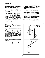
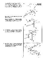
7. Attach one Backrest Tube (5) to the Backrest (6) with two M6 Washers (26) and two M6 x 38mm Screws (30). Attach the other Backrest Tube to the Backrest with one M6 Washer and one M6 x 38mm Screw. Note: Do not tighten the three Screws. The fourth M6 x 38mm Screw will be attached at the end of step 8. 7 ek------ 30 26 , o 5 1 \ 30 26 os °0 , 6 .\\.. 8. Press a 3/4" Round Inner Cap into each end of the Support Rod (7). Insert the Support Rod through one of the three sets of holes in the Uprights (1). Rotate the Support Rod to the locked position, with the end of the Support Rod clipped onto the Upright. See the inset drawing. Slide the ends of both Backrest Tubes (5) onto the pin oalhe Frame (2). Attach the free end of the Backrest Tube (5) to the Backrest (6) with one M6 Washer (26) and one M6 x 38mm Screw (30). Fully tighten all four M6 x 38mm Screws. 9. Attach the Seat (11) to the brackets on the Frame (2) with four M6 Washers (26) and four M6 x 16mm Screws (29). 8 1 6 a 6 5 . ~Si 26 30 9 5 . , 0 0 o 2 Pin 5 2 • -I 7 1 9 11 / / I I_ 10. Tap a Fly Arm Stop (15) onto each Upright (1). 2 . • 26 u--1 -29 26 29 10 1 15 8
-
 1
1 -
2
-
 3
3 -
 4
4 -
 5
5 -
 6
6 -
 7
7 -
 8
8 -
 9
9 -
 10
10 -
 11
11 -
 12
12 -
 13
13 -
14
-
15
-
16
 |
 |
