Weider 141 Bench User Manual - Page 6
Assembly
 |
View all Weider 141 Bench manuals
Add to My Manuals
Save this manual to your list of manuals |
Page 6 highlights
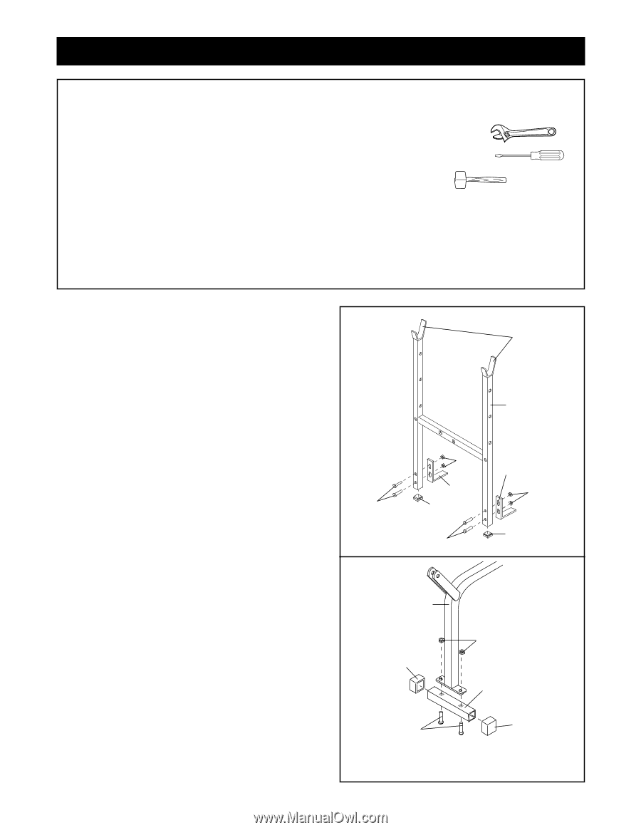
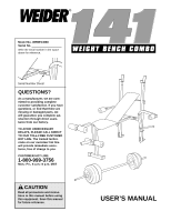
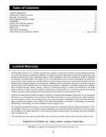
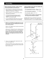
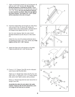
Assembly Before beginning assembly, carefully read the following information and instructions: • Place all parts in a cleared area and remove the packing materials; do not dispose of the packing materials until assembly is completed. • Tighten all parts as you assemble them, unless instructed to do otherwise. • For help identifying the small parts used in assembly, use the PART IDENTIFICATION CHART on the previous page. • As you assemble the weight bench, be sure that all parts are oriented as shown in the drawings. THE FOLLOWING TOOLS (NOT INCLUDED) ARE REQUIRED FOR ASSEMBLY: • Two (2) adjustable wrenches • One (1) standard screwdriver • One (1) rubber mallet • Lubricant, such as grease or petroleum jelly, and soapy water will also be needed. Assembly will be more convenient if you have the following tools: A socket set, a set of open-end or closed-end wrenches, or a set of ratchet wrenches. 1. Before you assemble the weight bench, be sure that you have read and understand the information in the box above. Press a 1 3/4" Square Inner Cap (21) into each side of the "H"-Frame (1). Attach each "L"-Bracket (12) to the indicated side of the "H"-Frame (1) with two 5/16" x 2 1/4" Bolts (16) and two 5/16" Jam Nuts (25) as shown. Be sure that the "H"-Frame (1) is oriented as shown. The high side of the weight rests must be on the side indicated. 2. Press a 1 1/2" Square Outer Cap (45) onto each end of the Stabilizer (3). Attach the Stabilizer (3) to the Main Frame (2) with the two 5/16" x 2" Carriage Bolts (27) and two 5/16" Nylon Locknuts (19). 1 High Side of Weight Rests 1 16 2 25 12 21 16 12 25 21 2 19 45 3 27 45 6
-
 1
1 -
 2
2 -
 3
3 -
 4
4 -
 5
5 -
 6
6 -
 7
7 -
 8
8 -
 9
9 -
 10
10 -
 11
11 -
 12
12 -
13
-
14
-
15
-
16
 |
 |