Weider 141 Bench User Manual - Page 8
Be sure the Backrest Bracket
 |
View all Weider 141 Bench manuals
Add to My Manuals
Save this manual to your list of manuals |
Page 8 highlights
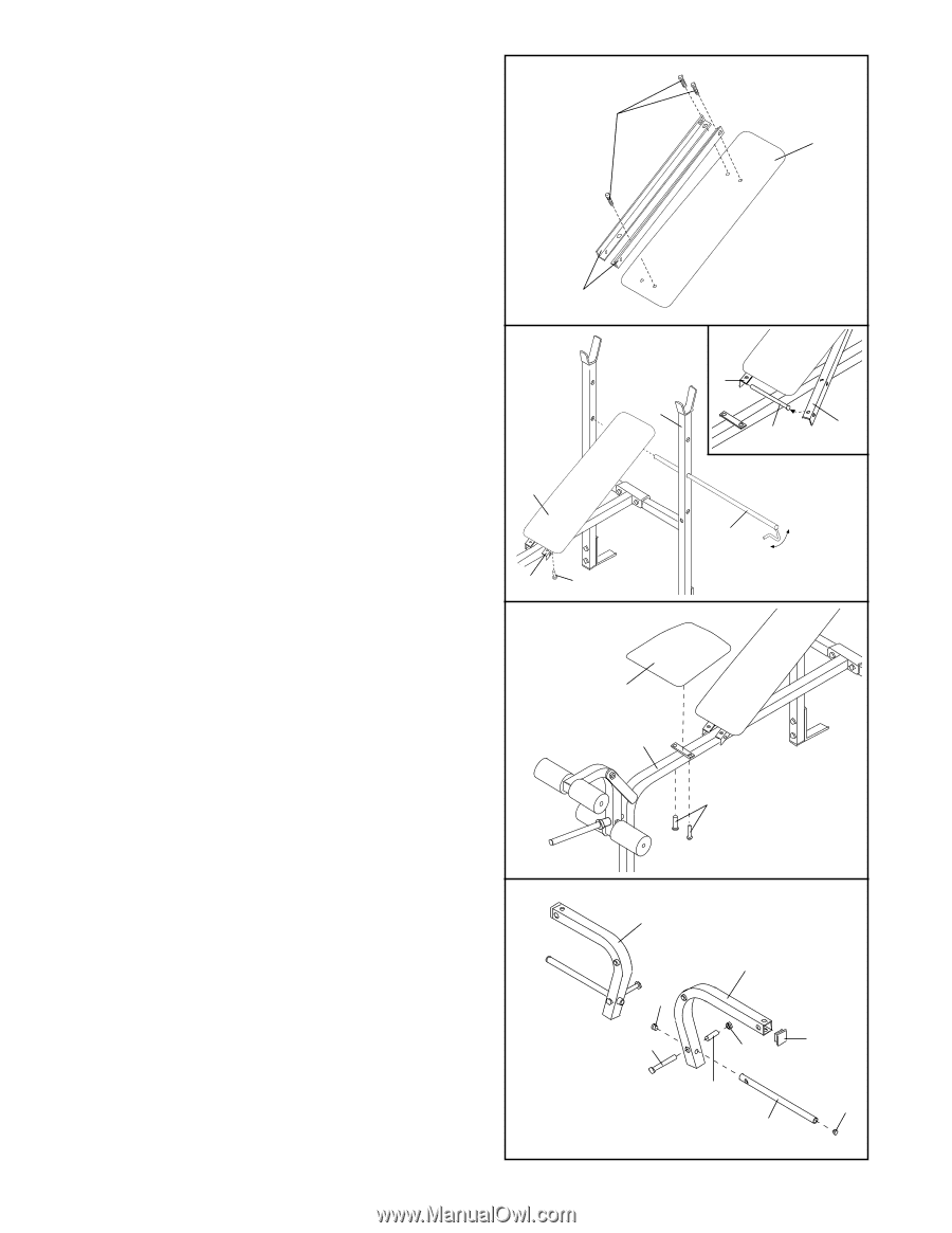
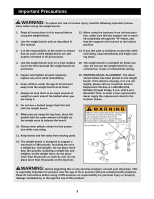
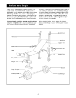
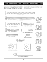
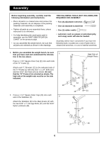
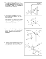
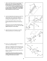
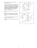
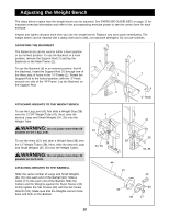
7. Attach one Backrest Bracket (5) to the Backrest (6) 7 with two 1/4" x 3/4" Screws (13). Be sure the Backrest Bracket is oriented as shown. Attach the other Backrest Bracket to the Backrest with one 13 1/4" x 3/4" Screw. Be sure the Backrest Bracket 6 is also oriented as shown. Note: Do not tighten the three Screws. The fourth 1/4" x 3/4" Screw will be attached at the end of step 8. 8. Insert the Support Rod (7) through one of the three sets of holes in the "H"-Frame (1). Rotate the Support Rod to the locked position, with the end of the Support Rod clipped onto the "H"-Frame. See the inset drawing. Slide the ends of both Backrest Brackets (5) onto the pin on the Frame (2). Attach the free end of the Backrest Bracket (5) to the Backrest (6) with a 1/4" x 3/4" Screw (13). Fully tighten all four 1/4" x 3/4" Screws. 5 8 6 5 1 2 5 7 9. Attach the Seat (11) to the bracket on the Main Frame (2) with two 1/4" x 3/4" Screws (13). 5 13 9 11 2 13 10. Press a 1 1/2" Square Cap (30) into the indicated end of one of the Fly Arms (42). 10 Attach an 11" Weight Tube (39) to the Fly Arm (42) with a 5/16" x 5" Bolt (32), a 1/2" x 3" Plastic Spacer (36), and a 5/16" Nylon Locknut (19) as shown. Press a 1" Round Cap (24) into each end of the 11" Weight Tube (39). Assemble the other Fly Arm (42) in the same manner; however this Fly Arm should be a mirror image of the first one, as shown. 8 42 24 32 42 19 36 39 30 24
-
 1
1 -
2
-
 3
3 -
 4
4 -
 5
5 -
 6
6 -
 7
7 -
 8
8 -
 9
9 -
 10
10 -
 11
11 -
 12
12 -
 13
13 -
14
-
15
-
16
 |
 |