Weider 8512 English Manual - Page 9
Weider 8512 Manual
 |
View all Weider 8512 manuals
Add to My Manuals
Save this manual to your list of manuals |
Page 9 highlights
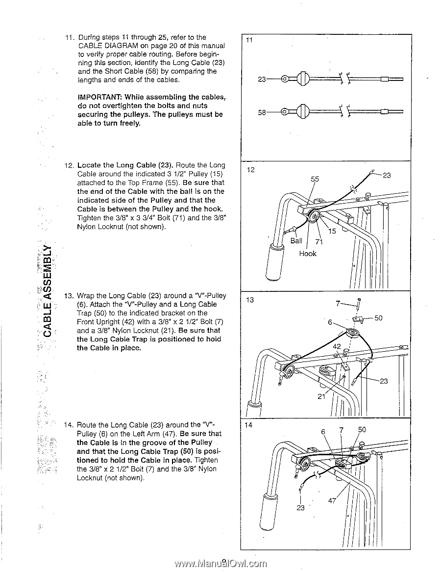
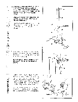
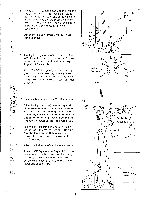
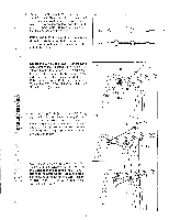
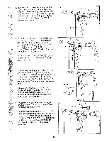
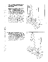
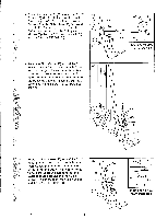
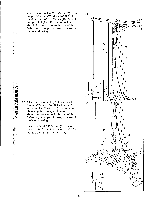
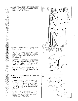
11. During steps 11 through 25, refer to the CABLE DIAGRAM on page 20 of this manual to verify proper cable routing. Before beginning this section, identify the Long Cable (23) and the Short Cable (58) by comparing the lengths and ends of the cables. IMPORTANT: While assembling the cables, do not overtighten the bolts and nuts securing the pulleys. The pulleys must be able to turn freely. 11 - 23 O - _ 58 O _ =1=i___I 12. Locate the Long Cable (23). Route the Long Cable around the indicated 3 1/2" Pulley (15) 12 attached to the Top Frame (55). Be sure that the end of the Cable with the ball is on the indicated side of the Pulley and that the Cable is between the Pulley and the hook. Tighten the 3/8" x 3 3/4" Bolt (71) and the 3/8" Nylon Locknut (not shown). 13. Wrap the Long Cable (23) around a "V"-Pulley (6). Attach the "V"-Pulley and a Long.Cable 13 Trap (50) to the indicated bracket on the Front Upright (42) with a 3/8" x 2 1/2" Bolt (7) and a 3/8" Nylon Locknut (21). Be sure that the Long Cable Trap is positioned to hold the Cable in place. 14. Route the Long Cable (23) around the "V"- 14 Pulley (6) on the Left Arm (47). Be sure that the Cable is in the groove of the Pulley and that the Long Cable Trap (50) is posi- tioned to hold the Cable in place. Tighten the 3/8" x 2 1/2" Bolt (7) and the 3/8" Nylon Locknut (not shown). 55 2 3 15 Ball 71 Hook 11 1 • 7_______, 6 • i4-50 42 i ,. 23 21 iII 6 7 50 - 47 ill 23 • a
-
 1
1 -
2
-
3
-
 4
4 -
 5
5 -
 6
6 -
 7
7 -
 8
8 -
 9
9 -
 10
10 -
 11
11 -
 12
12 -
 13
13 -
 14
14 -
15
-
16
-
17
-
18
-
19
-
20
 |
 |