Weider 8515 User Manual - Page 11
Weider 8515 Manual
 |
View all Weider 8515 manuals
Add to My Manuals
Save this manual to your list of manuals |
Page 11 highlights
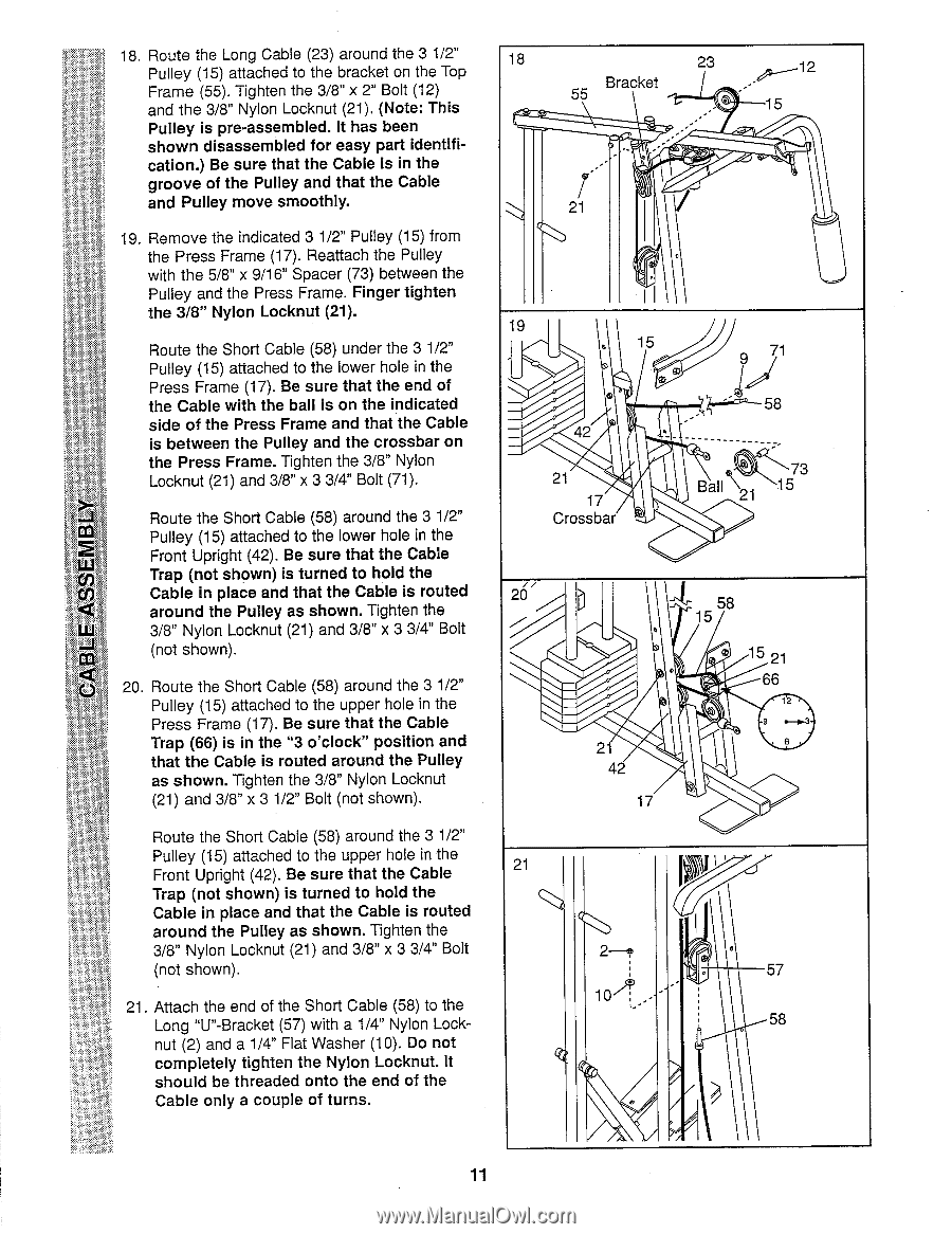
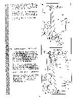
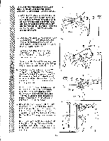
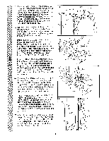
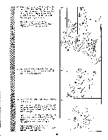
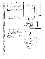
18. Route the Long Cable (23) around the 3 1/2" Pulley (15) attached to the bracket on the Top Frame (55). Tighten the 3/8" x 2" Bolt (12) and the 3/8" Nylon Locknut (21). (Note: This Pulley is pre-assembled. It has been shown disassembled for easy part identification.) Be sure that the Cable is in the groove of the Pulley and that the Cable and Pulley move smoothly. 19. Remove the indicated 3 1/2" Pulley (15) from the Press Frame (17). Reattach the Pulley with the 5/8" x 9/16" Spacer (73) between the Pulley and the Press Frame. Finger tighten the 3/8" Nylon Locknut (21). Route the Short Cable (58) under the 3 1/2" Pulley (15) attached to the lower hole in the Press Frame (17). Be sure that the end of the Cable with the ball is on the indicated side of the Press Frame and that the Cable is between the Pulley and the crossbar on the Press Frame. Tighten the 3/8" Nylon Locknut (21) and 3/8" x 3 3/4" Bolt (71). Route the Short Cable (58) around the 3 1/2" 2 Pulley (15) attached to the lower hole in the Front Upright (42). Be sure that the Cable Trap (not shown) is turned to hold the Cable in place and that the Cable is routed around the Pulley as shown. Tighten the 3/8" Nylon Locknut (21) and 3/8" x 3 3/4" Bolt CCI (not shown). 0 20. Route the Short Cable (58) around the 3 1/2" Pulley (15) attached to the upper hole in the Press Frame (17). Be sure that the Cable Trap (66) is in the "3 o'clock" position and that the Cable is routed around the Pulley as shown. Tighten the 3/8" Nylon Locknut (21) and 3/8" x 3 1/2" Bolt (not shown). Route the Short Cable (58) around the 3 1/2" Pulley (15) attached to the upper hole in the Front Upright (42). Be sure that the Cable Trap (not shown) is turned to hold the Cable in place and that the Cable is routed around the Pulley as shown. Tighten the 3/8" Nylon Locknut (21) and 3/8" x 3 3/4" Bolt (not shown). 21. Attach the end of the Short Cable (58) to the Long "U"-Bracket (57) with a 1/4" Nylon Locknut (2) and a 1/4" Flat Washer (10). Do not completely tighten the Nylon Locknut. It should be threaded onto the end of the Cable only a couple of turns. 18 23 Bracket ------12 55 ~ ji - ° 15 ,-21 19 . 15 ~j® 71 Z 11 ••";c'' 58 42 • 21 17 Crossbar Ball \21 15 26> 58 , 15 . 11 0 0 15 21 66 12 21 6 42 17 21 P I1 2--® 0 . . 57 58 . ? 11
-
 1
1 -
2
-
3
-
4
-
5
-
 6
6 -
 7
7 -
 8
8 -
 9
9 -
 10
10 -
 11
11 -
 12
12 -
 13
13 -
 14
14 -
 15
15 -
 16
16 -
17
-
18
-
19
 |
 |