Weider 8620 English Manual - Page 15
Decal Placement, Seat Assembly - home gym manual
 |
View all Weider 8620 manuals
Add to My Manuals
Save this manual to your list of manuals |
Page 15 highlights
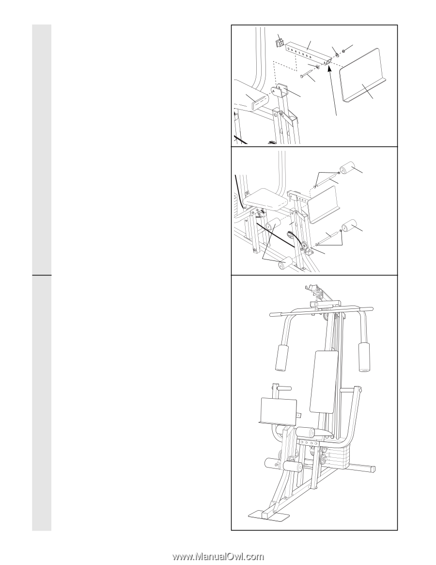
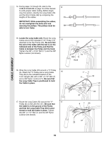
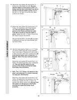
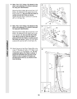
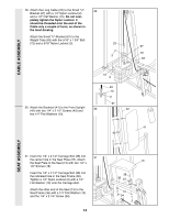
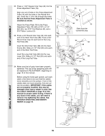
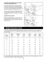
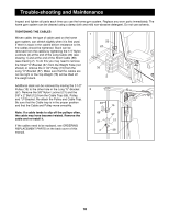
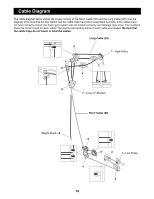
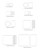
SEAT ASSEMBLY 32. Press a 1 3/4Ó Square Inner Cap (44) into the Press Adjustment Tube (79). Align one set of holes in the Press Adjustment Tube (79) with the holes in the Rocker Arm (32). Insert the ÒLÓ-Pin (40) through the holes. Be sure that the Press Adjustment Tube is oriented as shown. Attach the Press Plate (78) to the Press Adjustment Tube (79) with a 5/16Ó x 2 1/2Ó Bolt (22), two 5/16Ó Flat Washers (8), and a 5/16Ó Nylon Locknut (3). 33. Press a 3/4Ó Round Inner Cap (34) into each end of the Short Pad Tube (28). Press a 3/4Ó Round Inner Cap into each end of the Long Pad Tube (80). Insert the Short Pad Tube (28) into the Seat Frame (36). Slide a 5 1/2Ó Pad (30) onto each end of the Short Pad Tube. Insert the Long Pad Tube (80) into the Leg Lever (29). Slide a 5 1/2Ó Pad (30) onto each end of the Long Pad Tube. 34. Make sure that all parts have been properly tightened. The use of the remaining parts will be explained in ADJUSTMENT, beginning on page 16 of this manual. Before using the home gym system, pull each cable a few times to be sure that the cables move smoothly over the pulleys. If one of the cables does not move smoothly, find and correct the problem. IMPORTANT: If the cables are not properly installed, they may be damaged when heavy weight is used. See the CABLE DIAGRAM on page 19 of this manual for proper cable routing. If there is any slack in the cables, you will need to remove it by tightening the cables. See TROUBLE-SHOOTING AND MAINTENANCE on page 18. 32 44 79 8 3 8 22 40 32 78 Slant must be turned this way 33 34 30 28 36 30 34 80 30 34 29 DECAL PLACEMENT 15
-
 1
1 -
2
-
3
-
4
-
5
-
6
-
7
-
8
-
9
-
 10
10 -
 11
11 -
 12
12 -
 13
13 -
 14
14 -
 15
15 -
 16
16 -
 17
17 -
 18
18 -
 19
19 -
 20
20 -
21
-
22
-
23
-
24
-
25
 |
 |