Weider 8950 Uk Manual - Page 8
Arm Assembly
 |
View all Weider 8950 manuals
Add to My Manuals
Save this manual to your list of manuals |
Page 8 highlights
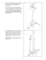
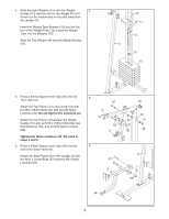
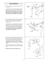
ARM ASSEMBLY 7. Press two 45mm Square Inner Caps (24) into the Leg Lever (9). Lubricate an M10 x 73mm Bolt (74) with grease. Attach the Leg Lever (9) to the Seat Frame (8) with the Bolt and an M10 Nylon Locknut (68). Make sure the warning decal is in the indicated position. Do not overtighten the Locknut; the Leg Lever must be able to pivot easily. 7 Warning 24 Decal 74 Lubricate 8 9 68 24 8. Press two 25mm x 50mm Inner Cap (25) into the top of the Press Frame (5). Press two 50mm Square Inner Caps (26) into the ends of the Press Frame. Lubricate an M10 x 125mm Bolt (64) with grease. Orient the Press Frame (5) with the bracket on the side shown. Attach the Press Frame to the Top Frame (4) with the Bolt, two M10 Washers (70), and an M10 Nylon Locknuts (68). Do not overtighten the Locknut; the Press Frame must be able to pivot easily. 8 64 25 4 Lubricate 26 70 68 70 5 26 Bracket 9. Press two 45mm Square Inner Caps (24) into the Left Arm (7). Press a 25mm Round Inner Cap (23) into the handle. Lubricate the indicated post with grease. Slide a 38mm x 50mm Round Bushing (28) onto the post on the Arm; make sure that the lip on the Bushing is oriented as shown. Attach an Arm Pad (20) to the Left Arm (7) with two M6 x 58mm Bolts (65) and two M6 Washers (73). Repeat this step with the Right Arm (6). 9 6 8 28 Lip Post 24 7 20 73 65 73 Handle 24 23
-
 1
1 -
2
-
 3
3 -
 4
4 -
 5
5 -
 6
6 -
 7
7 -
 8
8 -
 9
9 -
 10
10 -
 11
11 -
 12
12 -
 13
13 -
14
-
15
-
16
-
17
-
18
-
19
-
20
-
21
-
22
-
23
-
24
-
25
-
26
 |
 |
