Weider Club 500 English Manual - Page 9
Slide the Lat Tower 48 onto the Lat Tower Base
 |
View all Weider Club 500 manuals
Add to My Manuals
Save this manual to your list of manuals |
Page 9 highlights
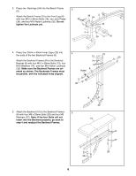
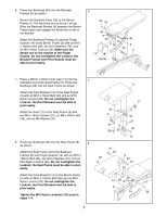
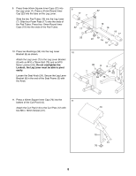
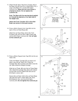
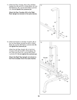
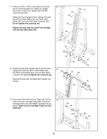
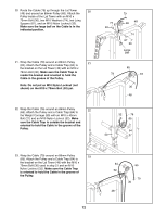
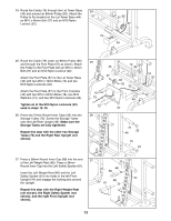
12. Attach the left side of the Front Crossbar (43) to the Base (42) with two M10 x 94mm Bolts (18), a Large Joint Plate (41), and two M10 Nylon Locknuts (32). Make sure the Joint Plates is oriented as shown. Do not tighten the Locknuts yet. 12 32 Note: The Base with the warning decal applied to it should be attached on the right side of the weight rack. Attach the Front Crossbar (43) to the other Base (not shown) in the same manner. 43 32 42 These holes are closer to this side of the Plate. 41 18 18 13. Press a 60mm Square Inner Cap (62) into the 13 back of the Lat Tower Base (49). Attach the Lat Tower Base (49) to the Front Crossbar (43) with two M10 x 68mm Bolts (26) and two M10 Nylon Locknuts (32). Do not tighten the Locknuts yet. 49 26 62 32 43 14. Press a 60mm Square Inner Cap (62) into the Lat Tower (48). Orient the Weight Carriage (50) as shown and slide it onto the Lat Tower (48). Orient the Carriage Stop (52) as shown and slide it onto the Lat Tower below the Weight Carriage. Slide the Lat Tower (48) onto the Lat Tower Base (49). Attach the Carriage Stop (52) at the indicated hole with an M10 x 86mm Bolt (35) and an M10 Nylon Locknut (32). Secure the Lat Tower (48) to the Lat Tower Base (49) with three M10 x 72mm Bolts (33), three M10 Washers (74), and three M10 Nylon Locknuts (32). Do not tighten the Locknuts yet. 14 62 48 33 74 33 32 Attach the Carriage Stop (52) here. 32 32 50 52 35 49 9
-
 1
1 -
2
-
3
-
 4
4 -
 5
5 -
 6
6 -
 7
7 -
 8
8 -
 9
9 -
 10
10 -
 11
11 -
 12
12 -
 13
13 -
 14
14 -
15
-
16
-
17
-
18
-
19
-
20
-
21
-
22
-
23
-
24
-
25
-
26
-
27
 |
 |
