Weider Platinum Xp600 Canadian English Manual - Page 14
Upper Cable Adjustment
 |
View all Weider Platinum Xp600 manuals
Add to My Manuals
Save this manual to your list of manuals |
Page 14 highlights
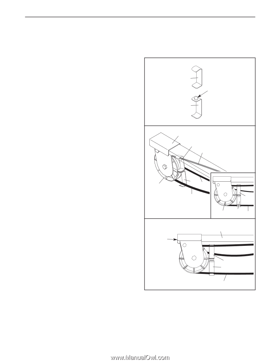
UPPER CABLE ADJUSTMENT After completing the assembly of the resistance system, the tension on the upper cable (B) will need to be adjusted. Also, the upper cable can stretch slightly when it is first used. When this occurs, the upper cable tension will need to be readjusted. Follow the steps below to adjust the upper cable tension. 1. Connect the two Tension Gauges (109, 110) 1 using the magnet. 109 Magnet 110 2. Plug in the resistance system as described in PLUGGING IN THE RESISTANCE SYSTEM on page 17. Use the Console (not shown) to adjust the resistance setting of the system to the highest setting, as described in ADJUSTING THE RESISTANCE on page 16. Squeeze the upper cable (B) together near a Large Pulley (17). Hook the ends of the Tension Gauges (109, 110) around the upper cable as shown. Do not hook the ends of the Tension Gauges around the Tether (61); which is attached to the back of the Pulley Bracket (10). Slide the Tension Gauges (109, 110) next to the Large Pulley (17) as shown in the inset drawing. 3. Locate the 3/8" x 1 1/2" Tension Screw (106) on each end of the Resistance Bar (9). Alternately tighten each Screw one turn at a time until the two Tension Gauges (109, 110) are pulled apart by the upper cable (B). The upper cable tension is now properly adjusted. 2 17 3 106 10 109 B 110 61 B 109 17 110 B 9 109 110 B 14
-
 1
1 -
2
-
3
-
4
-
5
-
6
-
7
-
8
-
 9
9 -
 10
10 -
 11
11 -
 12
12 -
 13
13 -
 14
14 -
 15
15 -
 16
16 -
 17
17 -
 18
18 -
 19
19 -
20
-
21
-
22
-
23
-
24
-
25
-
26
-
27
 |
 |