Weider Platinum Xp600 Canadian English Manual - Page 8
Sole May Be Damaged When The Power
 |
View all Weider Platinum Xp600 manuals
Add to My Manuals
Save this manual to your list of manuals |
Page 8 highlights
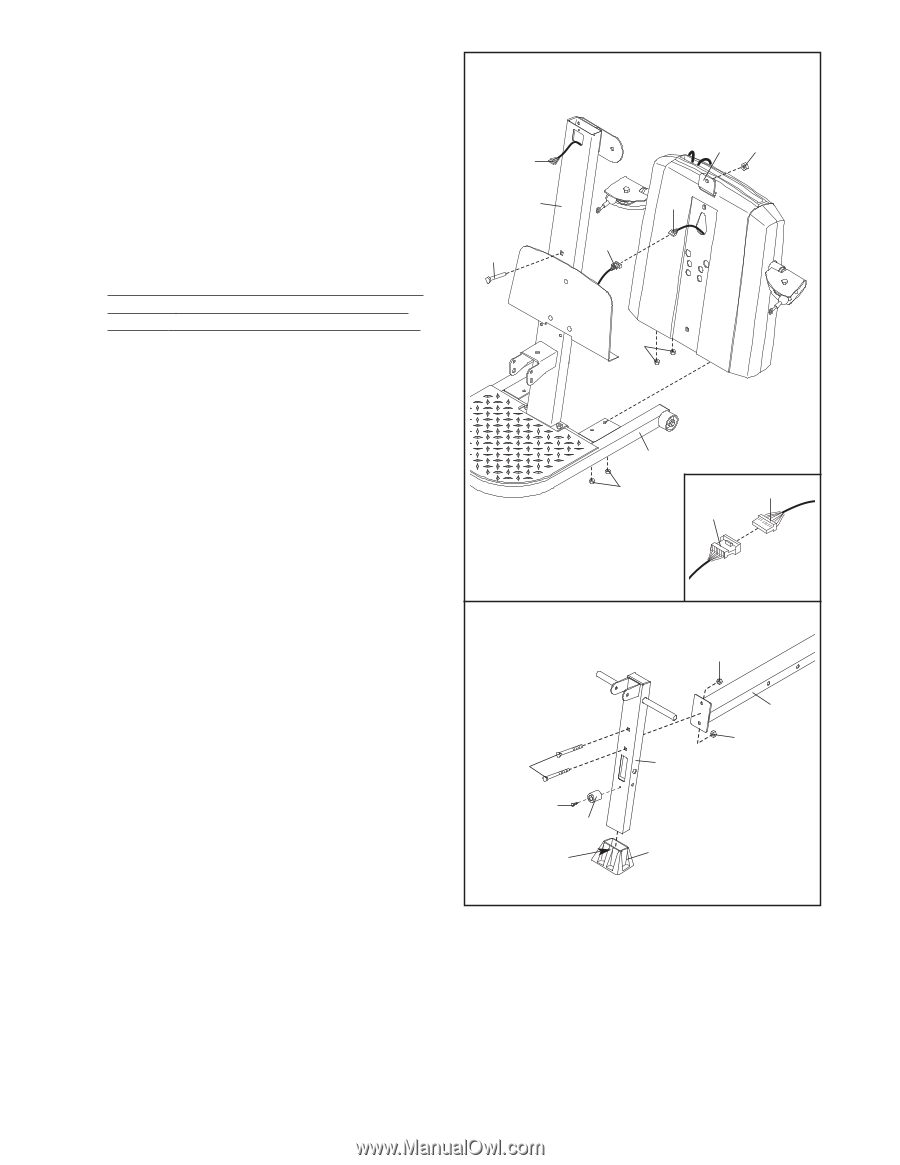
4. Insert the connector of the lower wire harness (A) into the socket of the Upper Wire Harness (13). The connector should slide easily into the socket and snap into place. If the connector does not slide easily and snap into place, turn the connector over and then insert it. Make sure that the connector and wire appear as shown in the inset drawing. IF THE CONNECTOR IS NOT INSERTED PROPERLY, THE CONSOLE MAY BE DAMAGED WHEN THE POWER IS TURNED ON. Pull the excess lower wire harness (A) out of the Mech Assembly (6) and push it and the Upper Wire Harness (13) into the Upright (3). Insert the Mech Assembly (6) into the Base (1). Attach the Mech Assembly to the Upright (3) with a 1/2" x 3" Carriage Bolt (79) and a 1/2" Nylon Locknut (78). Do not tighten the Locknut yet. Attach the Mech Assembly (6) to the Base (1) with the four M10 Nylon Locknuts (71). Tighten the 1/2" Nylon Locknut (78). 4 13 3 79 6 78 A 13 71 1 71 A 13 5. Press the Front Leg Foot (29) onto the bottom of the Front Leg (31). Note that the front of the Front Leg Foot is taller than the back. Attach the Leg Lever Bumper (30) to the Front Leg (31) with a #8 x 3/4" Screw (104). Attach the Bench Rail (23), with the hook on the bottom, to the Front Leg (31) with two 3/8" x 2" Carriage Bolts (91) and two 3/8" Nylon Jamnuts (92). 5 91 104 31 Front 92 23 92 31 29 8
-
 1
1 -
2
-
 3
3 -
 4
4 -
 5
5 -
 6
6 -
 7
7 -
 8
8 -
 9
9 -
 10
10 -
 11
11 -
 12
12 -
 13
13 -
14
-
15
-
16
-
17
-
18
-
19
-
20
-
21
-
22
-
23
-
24
-
25
-
26
-
27
 |
 |