Weider Pro 125 Bench Uk Manual - Page 5
Assembly - press
 |
View all Weider Pro 125 Bench manuals
Add to My Manuals
Save this manual to your list of manuals |
Page 5 highlights
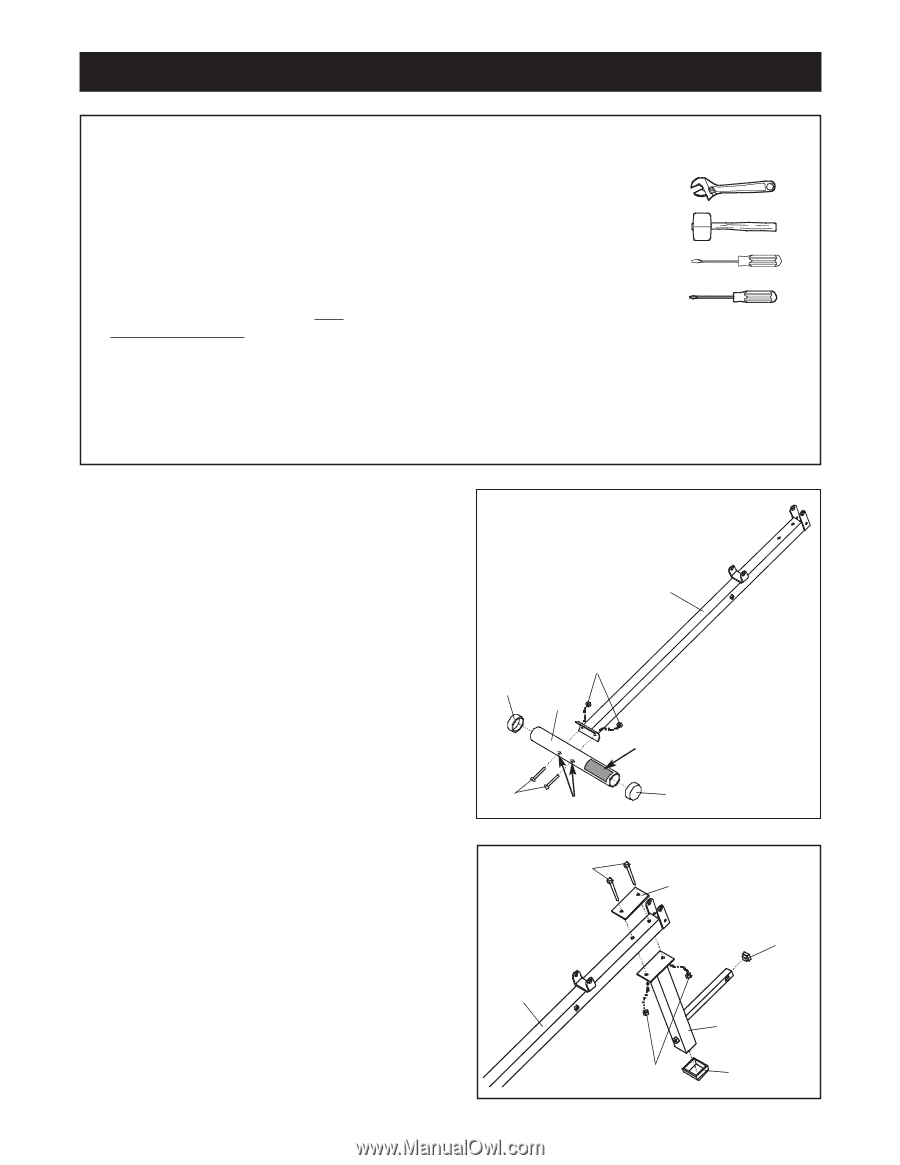
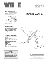
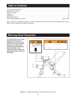
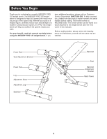
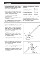
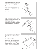
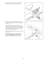
Assembly Before beginning assembly, carefully read the following information and instructions. If assistance is needed, call 08457 089 009. • Assembly requires two people. • Place all parts in a cleared area and remove the packing materials. Do not dispose of the packing materials until assembly is completed. • To identify small parts, use the Part Identification Chart in the centre of this manual. • Tighten all parts as you assemble them, unless instructed to do otherwise. • As you assemble the weight bench, make sure all parts are oriented as shown in the drawings. The following tools (not included) are required for assembly: • two adjustable spanners • one rubber mallet • one standard screwdriver • one phillips screwdriver • Lubricant, such as grease or petroleum jelly, and soapy water. Assembly will be more convenient if you have a socket set, a set of open-end or closed-end spanners, or a set of ratchet spanners. 1. Before assembling this product, make sure that you understand the information in the box above. Orient the Stabiliser (2) with the warning decal as shown. Insert two M10 x 72mm Carriage Bolts (21) through the holes in the Stabiliser so that the bolt heads fit into the indentations. Slide the bracket on the Main Frame (1) onto the two M10 x 72mm Carriage Bolts (21) in the Stabiliser (2). Make sure that the Main Frame is turned as shown. Tighten an M10 Nylon Locknut (18) onto each Carriage Bolt. Press a 60mm Round Endcap (10) onto each end of the Stabiliser (2). 1 1 18 10 2 Decal 21 Indentations 10 2. Press a Square Bushing (22) onto the lower end of the Leg (6). Press a 25mm Square Inner Cap (24) 2 19 into the tube on the Leg. Insert two M10 x 70mm Bolts (19) through the holes in the Support Plate (27) and then through the indicated holes in the Main Frame (1). Slide the bracket on the Leg (6) onto the two M10 x 70mm Bolts (19). Tighten two M10 Nylon Locknuts 1 (18) onto the Bolts. 27 24 6 18 22 5
-
 1
1 -
 2
2 -
 3
3 -
 4
4 -
 5
5 -
 6
6 -
 7
7 -
 8
8 -
 9
9 -
 10
10 -
 11
11 -
12
-
13
-
14
-
15
 |
 |