Weider Pro 300se English Manual - Page 6
the Front Stabilizer 3.
 |
View all Weider Pro 300se manuals
Add to My Manuals
Save this manual to your list of manuals |
Page 6 highlights
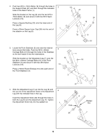
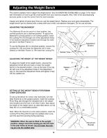
2. Push two M10 x 70mm Bolts (19) through the holes in 2 the Support Plate (27) and then through the indicated holes in the Main Frame (1). Slide the bracket on the Leg (6) onto the two M10 x 70mm Bolts (19) and secure it with two M10 Nylon Locknuts (18). Press a Square Bushing (22) onto the lower end of the Leg (6). 1 Press a 25mm Square Inner Cap (24) into the end of the sidearm on the Leg (6). 19 27 24 18 18 6 22 3. Locate the Front Stabilizer (3) and note the indentations around the holes. Push two M10 x 90mm Carriage Bolts (21) through the holes in the Stabilizer so the bolt heads fit into the indentations. Slide the bracket on the Adjustment Leg (7) onto the two M10 x 90mm Carriage Bolts (21) in the Front Stabilizer (3) and secure it with two M10 Nylon Locknuts (18). 3 18 10 7 18 Press a 76mm Round Endcap (10) onto each end of the Front Stabilizer (3). 3 10 4. Slide the Adjustment Leg (7) up into the Leg (6) and line up one of the adjustment holes in the Adjustment 4 Leg with the indicated hole in the Leg. Insert the Adjustment Knob (23) through the holes in both the Leg (6) and the Adjustment Leg (7). Tighten the Adjustment Knob fully into the welded nut. 1 21 6 Hole Welded Nut 23 7 6
-
 1
1 -
 2
2 -
 3
3 -
 4
4 -
 5
5 -
 6
6 -
 7
7 -
 8
8 -
 9
9 -
 10
10 -
 11
11 -
 12
12 -
13
-
14
-
15
 |
 |
