Weider Pro 300se English Manual - Page 8
Important: The Seat Frame 5 has two welded
 |
View all Weider Pro 300se manuals
Add to My Manuals
Save this manual to your list of manuals |
Page 8 highlights
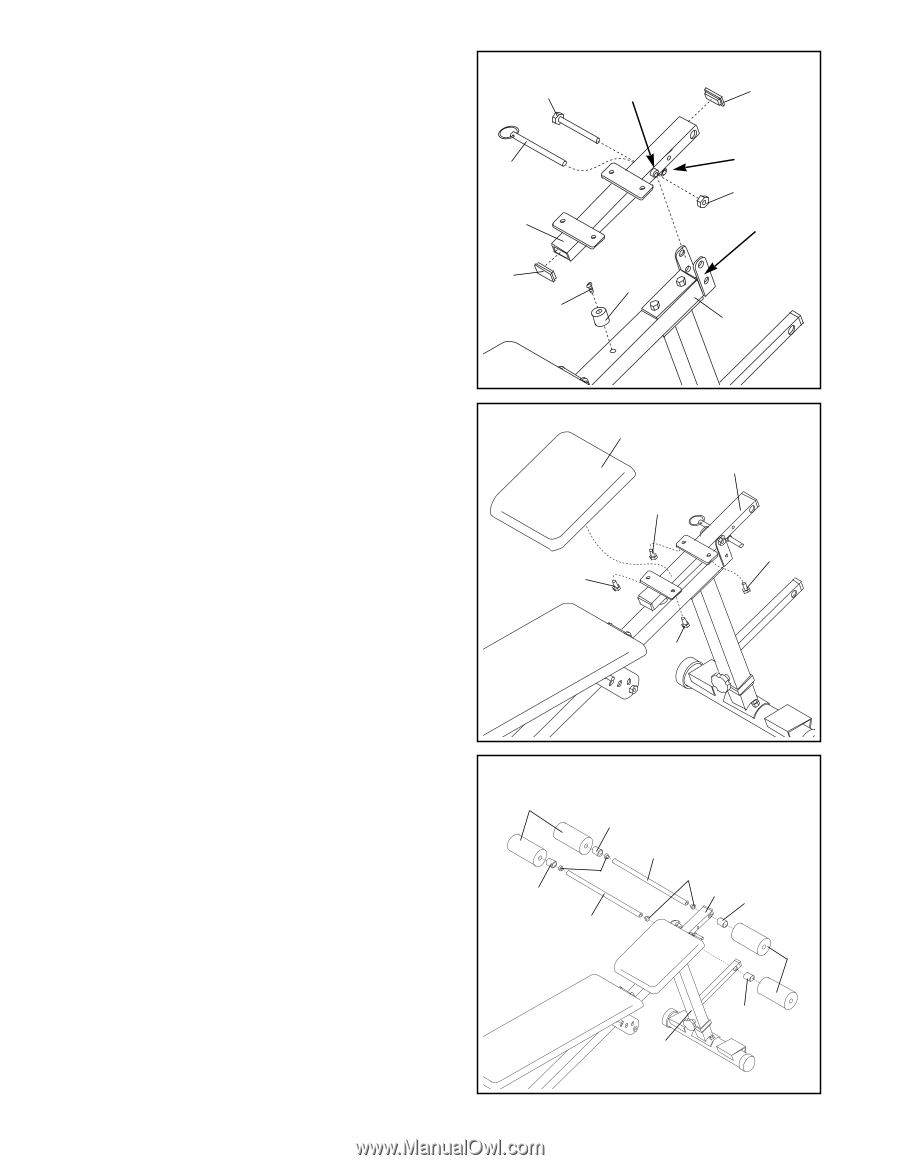
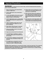
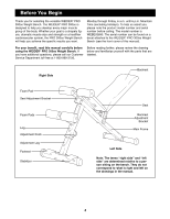
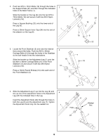
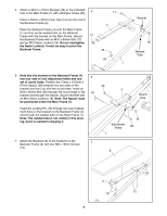
8. Attach a 30mm x 25mm Bumper (26) to the indicated hole in the Main Frame (1) with a Bumper Screw (25). Press a 25mm x 50mm Inner Cap (14) into each end of the Seat Frame (5). Important: The Seat Frame (5) has two welded tubes. Tube A goes through the Seat Frame itself, and tube B is welded underneath the Seat Frame. Do not confuse these two tubes in the following step. Line up tube A in the Seat Frame (5) with the upper hole in the bracket on the Main Frame (1). Insert the M10 x 95mm Bolt (20) through the bracket and the welded tube in the Seat Frame. Secure the Bolt with an M10 Nylon Locknut (18). Note: The Locking Pin w/Ring (30) can be inserted through tube B to prevent the Seat Frame (5) from pivoting. 9. Attach the Seat (9) to the brackets on the Seat Frame (5) with four M6 x 16mm Screws (15). 8 20 30 5 14 25 9 Welded Tube A 26 9 15 15 14 Welded Tube B 18 Bracket 1 5 15 15 10. Press a 19mm Round Inner Cap (13) into each end of the Short Pad Tube (31) and the Long Pad Tube (12). Mount the Long Pad Tube (12) in the hole in the Seat Frame (5) in the following manner: Slide a Plastic Spacer (32) and a Foam Pad (11) onto one end of the Pad Tube. Slide the Pad Tube through the hole in the Seat Frame. Slide a Plastic Spacer (32) and a Foam Pad (11) onto the other end of the Pad Tube. Mount the Short Pad Tube (31) in the hole in the sidearm on the Leg (6) by following the instructions given above. 10 11 32 32 13 31 12 13 5 32 11 32 6 8
-
 1
1 -
2
-
 3
3 -
 4
4 -
 5
5 -
 6
6 -
 7
7 -
 8
8 -
 9
9 -
 10
10 -
 11
11 -
 12
12 -
 13
13 -
14
-
15
 |
 |