Weider Pro 300se English Manual - Page 7
Note: The Spacer must
 |
View all Weider Pro 300se manuals
Add to My Manuals
Save this manual to your list of manuals |
Page 7 highlights
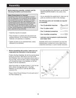
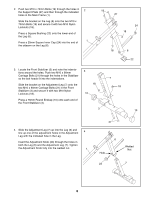
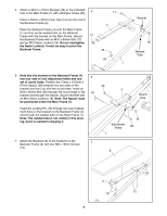
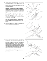
5. Attach a 30mm x 25mm Bumper (26) to the indicated 5 hole in the Main Frame (1) with a Bumper Screw (25). Press a 25mm x 50mm Inner Cap (14) into the end of the Backrest Frame (4). Place the Backrest Frame (4) onto the Main Frame (1) and line up the welded tube on the Backrest Frame with the bracket on the Main Frame. Secure 14 the Backrest Frame with an M10 x 80mm Bolt (17) and an M10 Nylon Locknut (18). Do not overtighten the Nylon Locknut; it must be easy to pivot the Backrest Frame. 17 4 25 26 1 Bracket 18 Welded Tube 6. Note that the bracket on the Backrest Frame (4) has four sets of oval adjustment holes and one 6 set of round holes. Position the 15mm x 10.5mm x 67mm Spacer (28) between the two sides of the bracket and line it up with the round holes. Insert an M10 x 85mm Bolt (29) through the round holes in the 16 bracket and through the Spacer. Secure the Bolt with an M10 Nylon Locknut (18). Note: The Spacer must be positioned under the Main Frame (1). Insert the Locking Pin (16) through one set of adjustment holes in the bracket on the Backrest Frame (4) and through the welded tube on the Main Frame (1). Note: The welded tube is not visible in this drawing, but it is marked in drawing 5. 7. Attach the Backrest (8) to the brackets on the Backrest Frame (4) with four M6 x 16mm Screws 7 (15). 29 4 Round Hole Adjustment Holes 1 18 28 8 4 15 15 7
-
 1
1 -
 2
2 -
 3
3 -
 4
4 -
 5
5 -
 6
6 -
 7
7 -
 8
8 -
 9
9 -
 10
10 -
 11
11 -
 12
12 -
13
-
14
-
15
 |
 |
