Weider Pro 335 Bench English Manual - Page 7
The 2 1/2 Square Bushing 22 must
 |
View all Weider Pro 335 Bench manuals
Add to My Manuals
Save this manual to your list of manuals |
Page 7 highlights
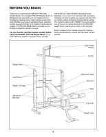
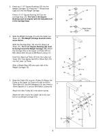
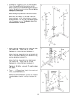
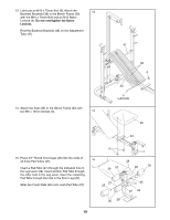
3. Press two 2 1/2" Square Bushings (22) into the 3 Weight Carriage (15). Press two 1" Round Inner Caps (21) into the Weight Carriage. Press a 2 1/2" Square Bushing (22) into the Carriage Stop (18). The hole in the Square Bushing must be aligned with the indicated hole in the Carriage Stop. 22 15 21 21 22 22 18 4. Slide the Weight Carriage (15) onto the Upper Lat Tower (41). The Weight Carraige must be orient- 4 ed as shown. Slide the Carriage Stop (18) onto the Upper Lat Tower (41). The 2 1/2" Square Bushing (22) must be facing toward the Weight Carriage (15). Attach the Carriage Stop to the Upper Lat Tower with an M8 x 68mm Bolt (8) and an M8 Nylon Locknut (7). Insert the Upper Lat Tower (41) into the Lower Lat Tower (23). Fully tighten the M10 x 56mm Bolt (19) into the Lower Lat Tower. Slide a Weight Stop (45) onto each side of the Weight Carriage (15). 15 8 45 18 19 Align these Holes 41 45 22 7 23 5. Wrap the Cable (10) around a Pulley (9). Attach the Pulley to the Upper Lat Tower (41) with an M10 x 70mm Bolt (12), two M10 Washers (13), two 14mm x 5 15mm Spacers (11), and an M10 Nylon Locknut (4). Attach the other Pulley (9) in the same manner. Attach the other end of the Cable (10) to the eyebolt on the Weight Carriage (15). 15 41 11 13 4 13 12 9 13 12 9 4 13 11 10 7
-
 1
1 -
 2
2 -
 3
3 -
 4
4 -
 5
5 -
 6
6 -
 7
7 -
 8
8 -
 9
9 -
 10
10 -
 11
11 -
 12
12 -
13
-
14
-
15
-
16
-
17
-
18
-
19
-
20
 |
 |
