Weider Pro 335 Bench English Manual - Page 9
M10 x 75mm Bolt and an M10 Nylon Locknut 4.
 |
View all Weider Pro 335 Bench manuals
Add to My Manuals
Save this manual to your list of manuals |
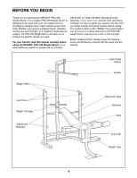
Page 9 highlights
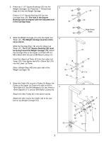
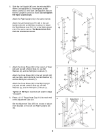
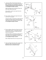
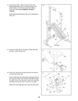
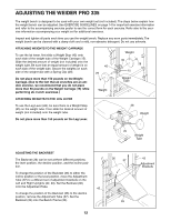
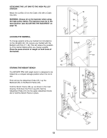
9. Lubricate an M10 x 75mm Bolt (5). Attach the Bench Frame (33) to the Cross Brace (30) with the M10 x 75mm Bolt and an M10 Nylon Locknut (4). The Bench Frame must be turned as shown. Do not overtighten the Nylon Locknut. 9 Lubricate 5 4 Attach the Bumper (24) to the Bench Frame (33) with an M4 x 25mm Screw (44). Press a 38mm x 50mm Inner Cap (16) into the 30 Bench Frame (33). 33 16 24 44 10. Press a 38mm x 50mm Inner Cap (16) into each end of the Front Leg (20). Lubricate an M10 x 75mm Bolt (5). Attach the Front Leg (20) to the Bench Frame (33) with the M10 x 75mm Bolt (5) and an M10 Nylon Locknut (4). Do not overtighten the Nylon Locknut. 10 33 16 4 20 5 Lubricate 11. Press two 38mm x 50mm Inner Caps (16) into the Leg Lever (28). Press a 1" Round Inner Cap (21) into the Front Leg. Press an Angled Round Cap (32) onto the Leg Lever. Lubricate an M10 x 75mm Bolt (5). Attach the Leg Lever (28) to the Front Leg (20) with the M10 x 75mm Bolt (5) and an M10 Nylon Locknut (4). Do not overtighten the Nylon Locknut. Slide a Weight Stop (45) onto the Leg Lever (28). 11 5 Lubricate 12. Attach both Backrest Brackets (38) to the Backrest (36) with four M6 x 16mm Screws (6). The 12 Backrests must be oriented as shown. 6 4 20 32 16 28 16 21 45 16 36 38 6 9
-
 1
1 -
2
-
3
-
 4
4 -
 5
5 -
 6
6 -
 7
7 -
 8
8 -
 9
9 -
 10
10 -
 11
11 -
 12
12 -
 13
13 -
 14
14 -
15
-
16
-
17
-
18
-
19
-
20
 |
 |
