Weider Pro 4000 Uk Manual - Page 12
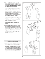
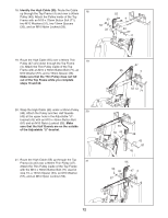
Identify the High Cable 55.
 |
View all Weider Pro 4000 manuals
Add to My Manuals
Save this manual to your list of manuals |
Page 12 highlights
18. Identify the High Cable (55). Route the Cable 18 up through the Top Frame (4) and over a 90mm Pulley (48). Attach the Pulley inside of the Top Frame with an M10 x 78mm Button Bolt (71), two M10 Washers (57), two 19mm Spacers (33), and an M10 Nylon Locknut (56). 57 56 33 55 4 48 33 57 71 19. Route the High Cable (55) over a 90mm Thin 19 Pulley (47) and down through the Top Frame (4). Attach the Thin Pulley inside of the Top Frame with an M10 x 78mm Button Bolt (71), an M10 Washer (57), and a 19mm Spacer (33). Make sure that the Thin Pulley does not fall out of the Top Frame while you complete steps 19 and 20. 20. Wrap the High Cable (55) under a 90mm Pulley 20 (48). Attach the Pulley and two Half Guards (43) at the upper hole in the Adjustable "U"- bracket (45) with an M10 x 45mm Button Bolt (81) and an M10 Nylon Locknut (56). Make sure that the Half Guards are on the outside of the Adjustable "U"-bracket. 21. Route the High Cable (55) up through the Top 21 Frame (4) and over a 90mm Thin Pulley (47). Attach the Thin Pulley inside of the Top Frame with the M10 x 78mm Button Bolt (71) used in step 19, a 19mm Spacer (33), an M10 Washer (57), and an M10 Nylon Locknut (56). 12 47 55 4 33 57 71 55 56 43 48 43 81 45 55 56 33 47 4 57 71
-
 1
1 -
2
-
3
-
4
-
5
-
6
-
 7
7 -
 8
8 -
 9
9 -
 10
10 -
 11
11 -
 12
12 -
 13
13 -
 14
14 -
 15
15 -
 16
16 -
 17
17 -
18
-
19
-
20
-
21
-
22
-
23
-
24
-
25
-
26
-
27
-
28
 |
 |
