Weider Pro 525 English Manual - Page 6
Assembly - rack system
 |
View all Weider Pro 525 manuals
Add to My Manuals
Save this manual to your list of manuals |
Page 6 highlights
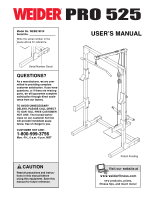
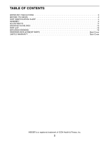
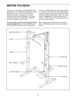
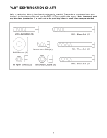
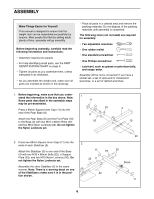
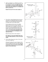
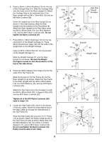
ASSEMBLY Make Things Easier for Yourself This manual is designed to ensure that the weight rack can be assembled successfully by anyone. Most people find that by setting aside plenty of time, assembly will go smoothly. Before beginning assembly, carefully read the following information and instructions: • Assembly requires two people. • For help identifying small parts, use the PART IDENTIFICATION CHART on page 5. • Tighten all parts as you assemble them, unless instructed to do otherwise. • As you assemble the weight rack, make sure all parts are oriented as shown in the drawings. • Place all parts in a cleared area and remove the packing materials. Do not dispose of the packing materials until assembly is completed. The following tools (not included) are required for assembly: • Two adjustable wrenches • One rubber mallet • One standard screwdriver • One Phillips screwdriver • Lubricant, such as grease or petroleum jelly, and soapy water. Assembly will be more convenient if you have a socket set, a set of open-end or closed-end wrenches, or a set of ratchet wrenches. 1. Before beginning, make sure that you understand the information in the box above. Note: Some parts described in the assembly steps may be pre-assembled. 1 11 Press a 60mm Square Inner Cap (11) into the end of the Rear Base (8). 20 8 Attach the Rear Base (8) and the Foot Plate (10) to the Base (3) with two M10 x 80mm Bolts (22) 20 and two M10 Nylon Locknuts (20). Do not tighten the Nylon Locknuts yet. 2. Press two 60mm Square Inner Caps (11) into the ends of each Stabilizer (5). Attach the Stabilizer (5) to one end of the Base (3) with two M10 x 80mm Bolts (22), a Support Plate (29), and two M10 Nylon Locknuts (20). Do not tighten the Nylon Locknuts yet. Assemble the other Stabilizer (5) in the same manner. Note: There is a warning decal on one of the Stabilizers; make sure it is in the position shown. 2 11 29 22 3 22 3 10 22 20 Decal 5 11 6
-
 1
1 -
 2
2 -
 3
3 -
 4
4 -
 5
5 -
 6
6 -
 7
7 -
 8
8 -
 9
9 -
 10
10 -
 11
11 -
 12
12 -
13
-
14
-
15
-
16
-
17
-
18
-
19
-
20
 |
 |