Weider Pro 7000 Uk Manual - Page 5
Passembly
 |
View all Weider Pro 7000 manuals
Add to My Manuals
Save this manual to your list of manuals |
Page 5 highlights
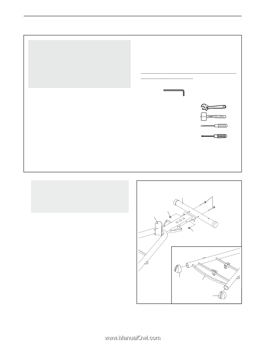
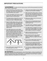
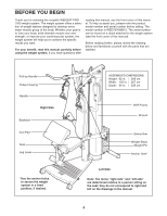
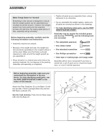
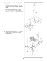
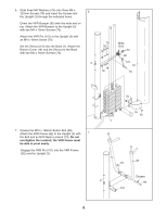
ASSEMBLY Make Things Easier for Yourself Everything in this manual is designed to ensure that the weight system can be assembled successfully by almost anyone. However, the weight system has many parts and the assembly process will take time. By setting aside plenty of time, assembly will go smoothly. Before beginning assembly, carefully read the following information and instructions: • Assembly requires two people. • Because of its weight and size, the weight system should be assembled in the location where it will be used. Make sure that there is enough clearance to walk around the weight system as you assemble it. • Place all parts in a cleared area and remove the packing materials. Do not dispose of the packing materials until assembly is completed. • Tighten all parts as you assemble them, unless instructed to do otherwise. • As you assemble the weight system, make sure all parts are oriented as shown in the drawings. • For help identifying small parts, use the PART IDENTIFICATION CHART. Assembly may be require the included grease and hex key , and the following tools (not included): • Two adjustable spanners • One rubber mallet • One standard screwdriver • One Phillips screwdriver • Clear tape or masking tape, and soapy water. Assembly will be more convenient if you have a socket set, a set of open-end or closed-end spanners, or a set of ratchet spanners. 1. Before beginning assembly, make sure you 1 understand the information in the box above. For help identifying small parts, use 5 59 the PART IDENTIFICATION CHART in the center of this manual. 74 1 Attach the Rear Stabilizer (5) to the Base (1) with the two M8 x 76mm Carriage Bolts (59) and two M8 Nylon Locknuts (74). 74 See the inset drawing. Press the two Base Caps (38) onto the Base (1). 38 1 38 5
-
 1
1 -
 2
2 -
 3
3 -
 4
4 -
 5
5 -
 6
6 -
 7
7 -
 8
8 -
 9
9 -
 10
10 -
 11
11 -
12
-
13
-
14
-
15
-
16
-
17
-
18
-
19
-
20
-
21
-
22
-
23
-
24
 |
 |