Weider Pro 9400 English Manual - Page 16
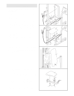
Wrap the Military Press Cable 72 around another
 |
View all Weider Pro 9400 manuals
Add to My Manuals
Save this manual to your list of manuals |
Page 16 highlights
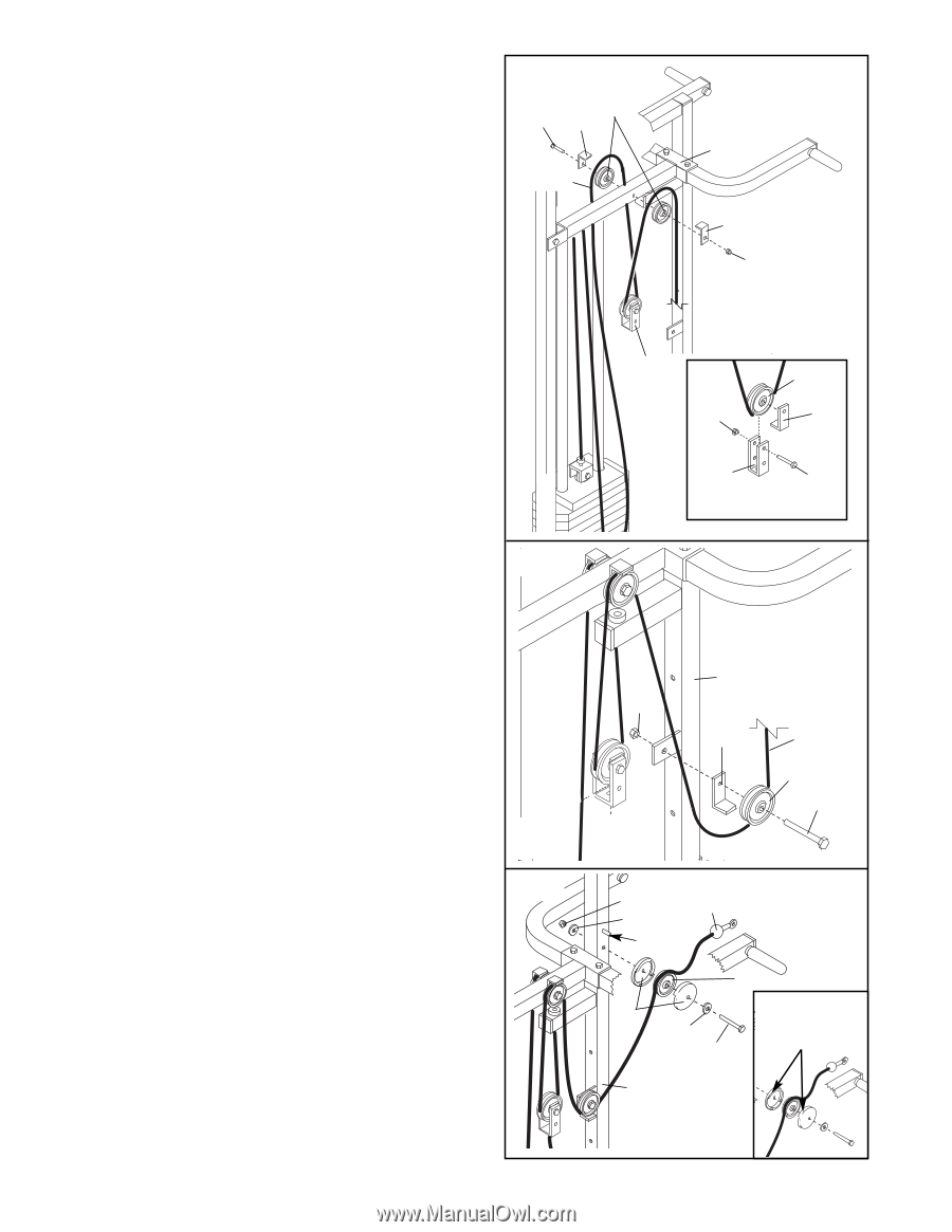
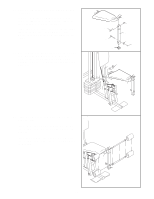
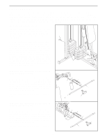
32. Wrap the Military Press Cable (72) around a 3 1/2" Pulley (15). Attach the Pulley and a Cable Trap (66) to the Pivot Arm (80) with the 3/8" x 5" Bolt (101). Be sure the Bolt is on the side shown, and that the Cable Trap is positioned to hold the Cable in place. Do not attach a locknut yet. See the inset drawing. Wrap the Military Press Cable (72) around a 3 1/2" Pulley (15). Attach the Pulley and a Cable Trap (66) to the upper hole in the Long "U"-Bracket (57) with a 3/8" x 2" Bolt (12) and a 3/8" Nylon Locknut (21). Be sure that the Cable Trap is inside the Long "U"-Bracket, that the Cable is in the groove of the Pulley, and that the Cable and Pulley move smoothly. Wrap the Military Press Cable (72) around another 3 1/2" Pulley (15). Attach the Pulley and a Cable Trap (66) to the 3/8" x 5" Bolt (101) on the other side of the Pivot Arm (80) with a 3/8" Nylon Locknut (21). Be sure that the Cable Trap is positioned to hold the Cable in place, and that the Cable is routed as shown. 32 15 101 66 72 57 80 66 21 15 21 66 57 12 33. Wrap the Military Press Cable (72) around a 3 1/2" 33 Pulley (15). Attach the Pulley and a Cable Trap (66) to the Leg Press Upright (56) with a 3/8" x 2" Bolt (12) and a 3/8" Nylon Locknut (21). Be sure the Cable Trap is positioned to hold the Cable in place. 56 21 66 72 15 12 34. Lay the Military Press Cable (72) over a 3 1/2" 34 Pulley (15). Attach the Pulley and both Pulley Covers (77) to the Leg Press Upright (56) with a 3/8" x 3 3/4" Bolt (88), two 3/8" Washers (9), and a 3/8" Nylon Jamnut (99). Make sure that the Military Press Cable (72) is between the 3 1/2" Pulley (15) and the post. Be sure that the Cable and Pulley move smoothly. The Pulley Covers (77) must be turned so that the large tabs face toward the weight system. See the inset drawing. 99 72 9 Post 15 Large tabs 77 9 must be in this location 88 56 16
-
 1
1 -
2
-
3
-
4
-
5
-
6
-
7
-
8
-
9
-
10
-
 11
11 -
 12
12 -
 13
13 -
 14
14 -
 15
15 -
 16
16 -
 17
17 -
 18
18 -
 19
19 -
 20
20 -
 21
21 -
22
-
23
-
24
-
25
-
26
-
27
-
28
-
29
-
30
-
31
-
32
-
33
 |
 |