Weider Pro 9400 English Manual - Page 5
Assembly - parts
 |
View all Weider Pro 9400 manuals
Add to My Manuals
Save this manual to your list of manuals |
Page 5 highlights
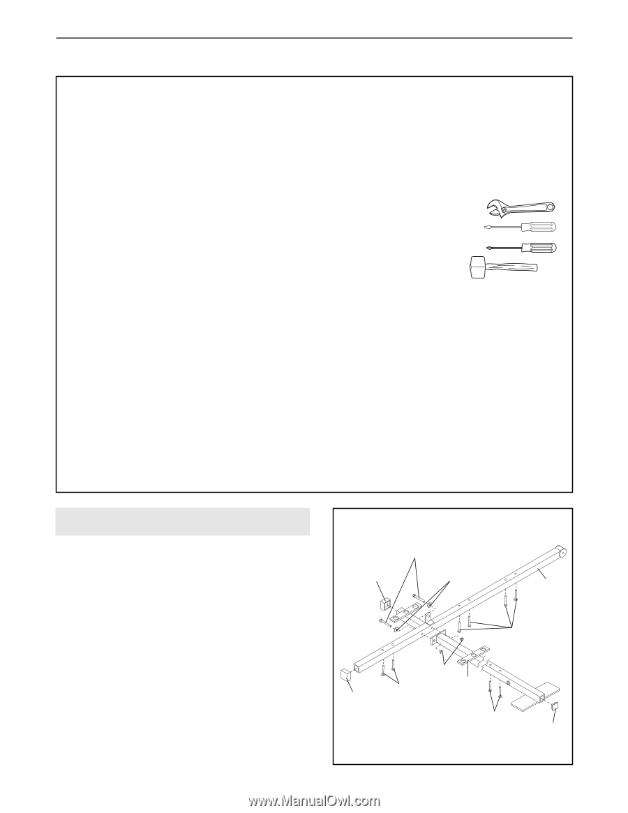
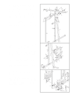
ASSEMBLY Before beginning assembly, carefully read the following information and instructions: • Due to the many features of the weight system, assembly will require several hours. By setting aside plenty of time and by deciding to make the task enjoyable, assembly will go smoothly. You may want to assemble the weight system over a couple of evenings. • Place all parts of the weight system in a cleared area and remove the packing materials; do not dispose of the packing materials until assembly is completed. • Assembly is divided into four stages: 1) frame assembly, 2) press and butterfly arm assembly, 3) cable and pulley assembly, and 4) seat and backrest assembly. The hardware for each stage is packaged separately. • Wait until you begin each assembly stage to open the parts bag labeled for that assembly stage. • For help identifying the small parts used in assembly, use the PART IDENTIFICATION CHART located in the center of this manual. Note: Some small parts may have been preattached for shipping. If a part is not in the parts bag, check to see if it has been pre-attached. • Tighten all parts as you assemble them, unless instructed to do otherwise. • Assembly requires two persons. For your convenience and safety, assemble the weight system with the help of another person. • As you assemble the weight system, be sure that all parts are oriented as shown in the drawings. THE FOLLOWING TOOLS (NOT INCLUDED) ARE REQUIRED FOR ASSEMBLY: • Two (2) adjustable wrenches • One (1) standard screwdriver • One (1) phillips screwdriver • One (1) rubber mallet • Lubricant, such as grease or petroleum jelly, and soapy water will also be needed. • Assembly will be more convenient if you have the following tools: A socket set, a set of open-end or closed-end wrenches, or a set of ratchet wrenches. Questions? • If you have questions after reading the assembly instructions, please call our Customer Service Department toll-free at 1-800-999-3756, Monday through Friday, 6 a.m. until 6 p.m. Mountain Time. FRAME ASSEMBLY 1 1. Before beginning, be sure that you have read and understand the information in the box above. Locate and open the parts bag labeled "FRAME ASSEMBLY." Press two 2" Square Outer Caps (51) onto the indicated locations on the Stabilizer (5). Press a 2" Square Inner Cap (27) into the end of the Base (4). Insert six 5/16" x 2 1/2" Carriage Bolts (1) up through the Stabilizer (5). Insert two 5/16" x 2 1/2" Carriage Bolts up through the Base (4). Attach the Base (4) to the Stabilizer (5) with two 5/16" x 2 3/4" Bolts (11), two 5/16" Washers (8), and two 5/16" Nylon Locknuts (3). Do not tighten the Nylon Locknuts yet. 5 11 51 8 5 1 3 1 4 51 1 27
-
 1
1 -
 2
2 -
 3
3 -
 4
4 -
 5
5 -
 6
6 -
 7
7 -
 8
8 -
 9
9 -
 10
10 -
 11
11 -
12
-
13
-
14
-
15
-
16
-
17
-
18
-
19
-
20
-
21
-
22
-
23
-
24
-
25
-
26
-
27
-
28
-
29
-
30
-
31
-
32
-
33
 |
 |