Weider Pro Lx7 English Manual - Page 9
Backrest must be able to move freely.
 |
View all Weider Pro Lx7 manuals
Add to My Manuals
Save this manual to your list of manuals |
Page 9 highlights
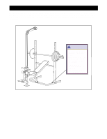
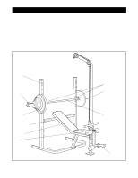
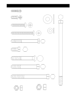
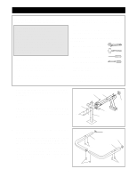
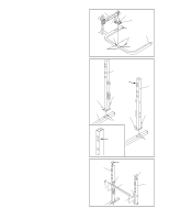
6. Insert four 1" Square Caps (22) into the ends of the Backrest Tubes (11). Attach the Backrest (13) to the Backrest Tubes (11) with four M6 x 38mm Screws (35) and four M6 Washers (39). Do not tighten the Screws yet. Make sure the Backrest Tubes are oriented as shown. 7. Lubricate an M10 x 175mm Bolt (29). Attach the Backrest Tubes (11) to the Bench Frame (1) with the Bolt and an M10 Nylon Locknut (37). Do not overtighten the Nylon Locknut; the Backrest must be able to move freely. Tighten the four Screws (35) from the previous step. Lower the Backrest (13) onto the Support Tube (8). 8. Attach one end of the Seat (14) to the Bench Frame (1) with the M6 x 62mm Screw (32) and an M6 Washer (39). Attach the other end of the Seat (14) with two M6 x 16mm Screws (33). 6 13 22 22 35 11 39 39 35 7 29 Lubricate 11 13 8 37 1 8 14 33 1 9. Press a 2" Round Cap (25) into the end of the weight 9 tube (C). Press a 50 x 50mm Square Cap (20) into each end of the Leg Lever (3). Attach the Bumper (24) to the Front Leg (2) with an M4 x 19mm Screw (34). 33 32 39 20 3 2 25 C 20 24 34 9
-
 1
1 -
2
-
3
-
 4
4 -
 5
5 -
 6
6 -
 7
7 -
 8
8 -
 9
9 -
 10
10 -
 11
11 -
 12
12 -
 13
13 -
 14
14 -
15
-
16
-
17
-
18
-
19
-
20
-
21
-
22
-
23
 |
 |
