Weslo 450t Stepper English Manual - Page 6
Connect the Reed Switch Wire 12 to
 |
View all Weslo 450t Stepper manuals
Add to My Manuals
Save this manual to your list of manuals |
Page 6 highlights
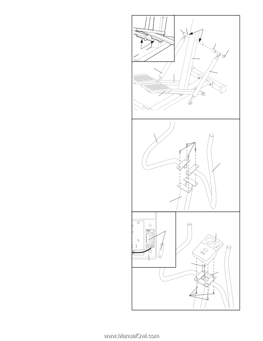
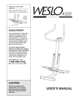
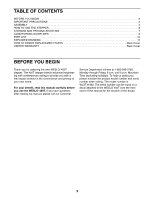
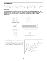
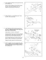
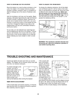
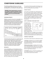
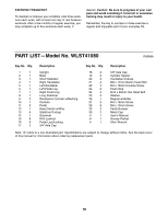
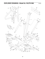
6. Apply grease to the shafts on the Upright (1). Slide a Cylinder Spacer (19) and a Resistance Cylinder (9) onto each of the shafts on the Upright (1). Make sure that the indented sides of the Cylinder Spacers are facing the Upright. Tap a 5/8Ó Axle Cap (18) onto each shaft. Raise the Left Pedal Leg (6) and rest it on the hook at the lower end of the left Resistance Cylinder (9). The hook must be in one of the slots under the Left Pedal Leg as shown in the inset drawing. Raise the Right Pedal Leg (7) and rest it on the hook at the lower end of the right Resistance Cylinder (9). Make sure that the hooks are in the same position under both Pedals. 7. Attach the Right Handlebar (4) to the Upright (1) with two M6 x 12mm Button Head Bolts (21). Attach the Left Handlebar (5) to the Upright (1) in the same manner. 6 Slots 9 7 7 5 18 19 Apply Grease 19 18 1 6 9 21 4 1 8. Refer to the inset drawing. The Console (10) 8 requires two ÒAAÓ batteries (not included). Alkaline batteries are recommended. Press two batteries into the battery clip under the Console. Batteries 10 Make sure that the negative (Ð) ends of the batteries are touching the springs. Connect the Reed Switch Wire (12) to the Console (10). Attach the Console (10) to the Upright (1) with 10 four M4 x 16mm Console Screws (22). Be care- ful to avoid pinching the Reed Switch Wire (12). 12 1 22 9. Make sure that all parts are properly tightened before you use the stepper. 6
-
 1
1 -
 2
2 -
 3
3 -
 4
4 -
 5
5 -
 6
6 -
 7
7 -
 8
8 -
 9
9 -
 10
10 -
 11
11 -
 12
12
 |
 |