Weslo Bench 500 User Manual - Page 6
Assembly
 |
View all Weslo Bench 500 manuals
Add to My Manuals
Save this manual to your list of manuals |
Page 6 highlights
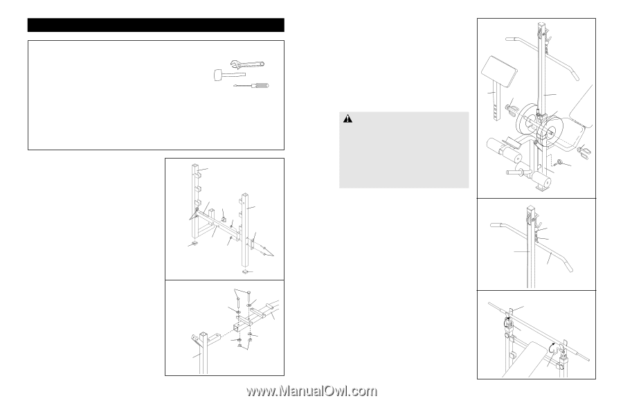
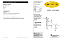
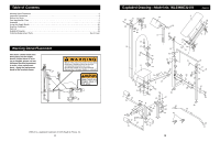
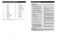
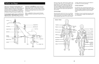
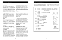
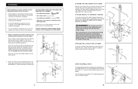
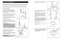
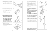
Assembly Before beginning assembly, carefully read the following information and instructions: • Place all parts in a cleared area and remove the packing materials; do not dispose of the packing materials until assembly is completed. • Tighten all parts as you assemble them, unless instructed to do otherwise. • For help identifying the small parts used in assembly, use the PART IDENTIFICATION CHART on the page 5. • As you assemble the weight bench, be sure that all parts are oriented as shown in the drawings. THE FOLLOWING TOOLS (NOT INCLUDED) ARE REQUIRED FOR ASSEMBLY: • Two adjustable spanners • One rubber mallet • One standard screwdriver • Lubricant, such as grease or petroleum jelly, and soapy water. A socket set, a set of end spanners, or a set of ratchet spanners is recommended. If further assistance is needed, please call our Customer Service Department at 0345-089009. 1. Before assembling this product, make sure you understand the information in the box above. Press a 50mm x 50mm Square Inner Cap (36) into the lower end of each Upright (1, 15). Press a 45mm x 45mm Square Inner Cap (28) into the end of the base of the Right Upright (1). Orient the Crossbar (3) with the warning decal facing up as shown. Attach the Crossbar to the Left Upright (15) with two M10 x 70mm Bolts (26), a Support Plate (14) and two M10 Nylon Locknuts (30). The Upright must be oriented as shown. Attach the Crossbar (3) to Right Upright (1) in the same manner. 2. Attach the Frame (2) to the welded bracket on the Front Leg (8) with two M8 x 50mm Bolts (44), four M8 Washers (17) and two M8 Nylon Locknuts (34). 1 1 Decal 28 30 30 3 36 30 15 14 26 36 2 44 17 17 2 17 17 34 8 6 ATTACHING THE CURL UPRIGHT OR LAT TOWER Slide the Curl Upright (13) or Lat Tower (23) into the Front Leg (8). Align one of the adjustment holes in the Curl Upright or Lat Tower with the adjustment hole in the Front Leg. Tighten the Small Threaded Knob (19) into the adjustment hole in the Front Leg. ATTACHING WEIGHTS TO THE WEIGHT CARRIAGE To use the Lat Tower (23), slide the desired amount of weight (not included) onto the weight tubes on the Weight Carriage (42). Secure the weights with the Spring 13 45 Clips (45, not shown). WARNING: Do not place more than 50 kg on the weight carriage. Always place the same amount of weight on each side of the weight carriage. When performing an exercise during whilst sitting on the bench with your back to the lat tower, make sure there is plenty of space between your back and the weight carriage. Always lower the weight carriage in a controlled manner. Never let the weight carriage drop. ATTACHING THE LAT BAR TO THE LAT TOWER To use the Lat Tower (23), attach the Lat Bar (48) to the Cable (38) with a Cable Clip (37). Slide the Handgrips (43) onto each end of the Lat Bar (48). 23 23 42 45 19 8 38 37 48 USING THE BARBELL HOOKS To change weights while your barbell (not included) is on 16 the Weight Rests (16), secure the barbell with the Barbell Hooks (46, 47). To do this, flip the Barbell Hooks over the barbell. 46 This will reduce the possibility of the barbell tipping while you are changing weights. 47 11
-
 1
1 -
 2
2 -
 3
3 -
 4
4 -
 5
5 -
 6
6 -
 7
7 -
 8
8
 |
 |