Weslo Cadence 1000 Fm Uk Manual - Page 8
Serted Properly, The Console May Be Dam - static
 |
View all Weslo Cadence 1000 Fm manuals
Add to My Manuals
Save this manual to your list of manuals |
Page 8 highlights
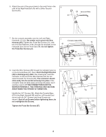
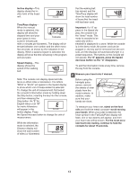
6. Attach the end of the ground wire to the small hole in the 6 side of the Right Handrail (40) with a Silver Ground Screw (66). 40 66 Ground Wire 7. Set the console assembly onto the Left and Right Handrails (13, 40). Be careful not to pinch the Wire Harness (65). Tighten two Pulse Bar Screws (37), with two #10 Star Washers (108), through the brackets on the Handrails and into the Pulse Bar (39). Do not tighten the Pulse Bar Screws yet. 7 Console Assembly 40 65 108 39 37 13 108 37 8. Insert the Wire Harness (65) through the indicated nylon tie on the Console Base (67). Next, touch the Right Handrail (40) to discharge any static. See drawing 8a. Insert the connector on the end of the Wire Harness into the red socket beneath the Console (69). The connector should slide easily into the socket and snap into place. If the connector does not slide easily and snap into place, turn it and then insert it. IF THE CONNECTOR IS NOT INSERTED PROPERLY, THE CONSOLE MAY BE DAMAGED WHEN THE POWER IS TURNED ON. Identify the 3/4" Screws (38). Attach the Console Base (67) to the Right Handrail (40) and the Left Handrail (not shown) with six 3/4" Screws (only three Screws are shown). Start all six Screws before tightening them; do not overtighten the Screws. Tighten the Pulse Bar Screws (37). 8 38 40 37 8a 65 67 Tie 69 65 8
-
 1
1 -
2
-
 3
3 -
 4
4 -
 5
5 -
 6
6 -
 7
7 -
 8
8 -
 9
9 -
 10
10 -
 11
11 -
 12
12 -
 13
13 -
14
-
15
-
16
-
17
-
18
-
19
-
20
-
21
-
22
-
23
-
24
 |
 |
