Weslo Cadence 5.0 Treadmill Uk Manual - Page 6
Assembly, Warning
 |
View all Weslo Cadence 5.0 Treadmill manuals
Add to My Manuals
Save this manual to your list of manuals |
Page 6 highlights
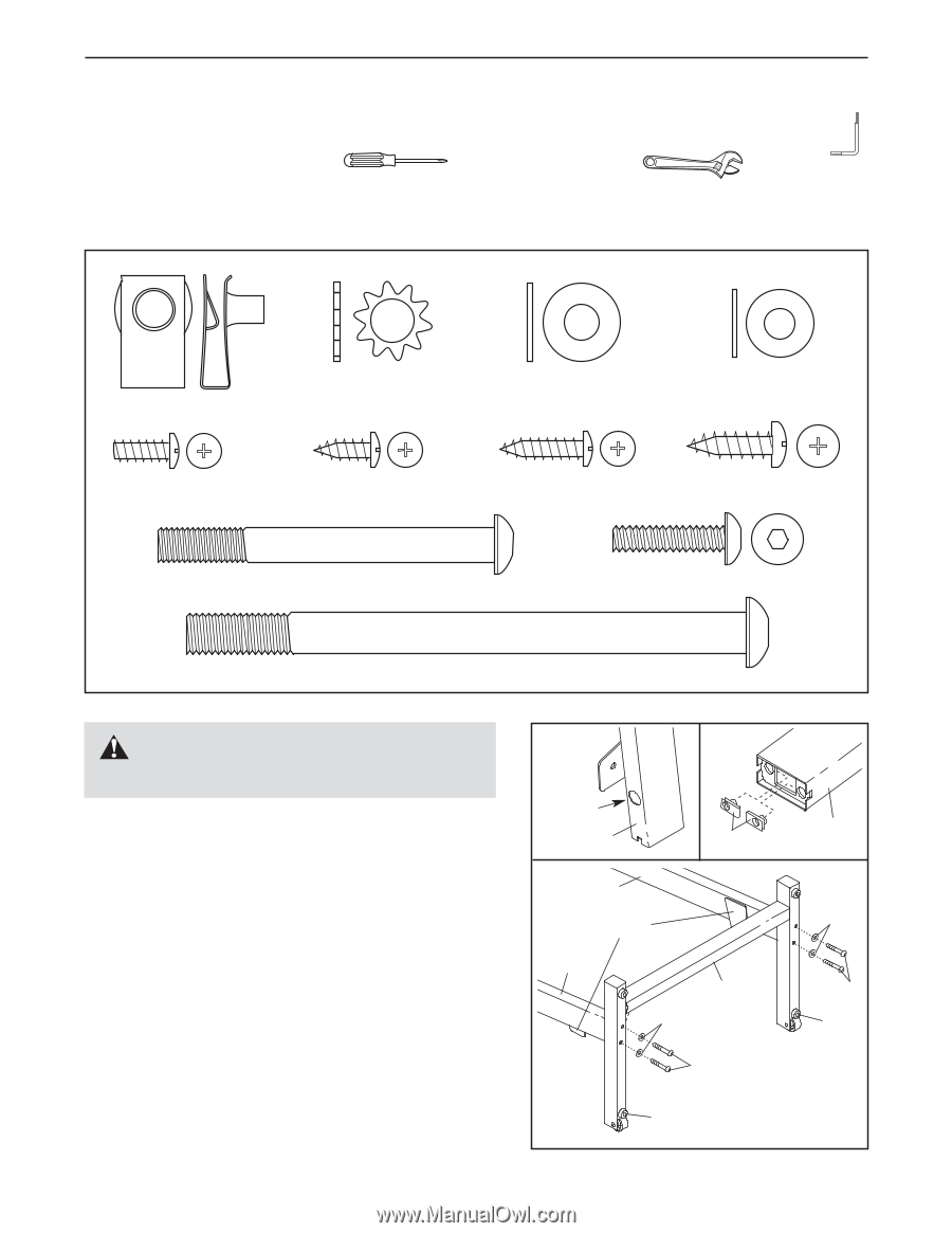
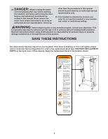
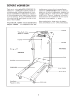
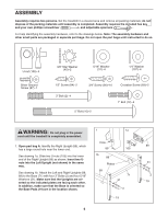
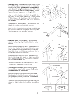
ASSEMBLY Assembly requires two persons. Set the treadmill in a cleared area and remove all packing materials; do not dispose of the packing materials until assembly is completed. Assembly requires the included hex key and your own phillips screwdriver and adjustable spanners . For help identifying the assembly hardware, refer to the drawings below. Note: The assembly hardware and other small parts are packaged in separate part bags. Do not open the part bags until instructed to do so. U-nut (105)-4 Silver Ground Screw (87)-1 3/8" Star Washer (45)-2 5/16" Washer (31)-4 1/4" Washer (107)-4 1/2" Screw (84)-2 3/4" Screw (90)-10 Crossbar Screw (69)-2 3" Bolt (2)-4 5" Bolt (10)-2 1" Bolt (12)-4 WARNING: Do not plug in the power cord until the treadmill is completely assembled. 1. Open part bag A. Identify the Right Upright (89), which has a large round hole near the lower end. See drawing 1a. Slide two U-nuts (105) into the lower end of the Right Upright (89) as shown. Insert two Unuts into the Left Upright (not shown) in the same way. See drawing 1b. Attach the Left and Right Uprights (88, 89) to the Base (71) with four 3" Bolts (2) and four 5/16" Washers (31). Make sure that the Uprights are oriented so the indicated plates are facing each other. In addition, make sure that the Base is oriented so the Base Pads (19) are in the location shown. 1 1a Hole 89 105 1b 88 Plates 89 71 31 2 19 6 89 31 2 19
-
 1
1 -
 2
2 -
 3
3 -
 4
4 -
 5
5 -
 6
6 -
 7
7 -
 8
8 -
 9
9 -
 10
10 -
 11
11 -
 12
12 -
13
-
14
-
15
-
16
-
17
-
18
-
19
-
20
-
21
-
22
-
23
 |
 |