Weslo Cadence 620 User Guide - Page 9
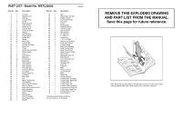
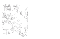
REMOVE THIS EXPLODED DRAWING, AND PART LIST FROM THE MANUAL., Save this for future reference.
 |
View all Weslo Cadence 620 manuals
Add to My Manuals
Save this manual to your list of manuals |
Page 9 highlights
PART LISTÑModel No. WETL20000 R0800A Key No. Qty. 1 1 2 1 3 1 4 1 5 12 6 1 7 1 8 1 9 3 10 2 11 4 12 4 13 2 14 2 15 2 16 2 17 5 18 1 19 4 20 1 21 1 22 1 23 1 24 8 25 1 26 18 27 2 28 2 29 2 30 3 31 2 32 1 33 3 34 4 35 1 36 1 37 1 38 1 39 1 40 1 41 7 42 5 43* 1 44 1 45 1 46 1 47 4 48 1 49 1 Description Console Speed Control Key/Clip Console Plate Screw Right Handrail Left Handrail Battery Cover Console Bolt Frame Pivot Bolt Washer Handrail Bolt Frame Spacer Wheel Bolt Wheel Base Cap Handrail Nut Handrail Grommet Base Pad Choke Incline Warning Decal Wire Harness Hood Hood Screw Belly Pan Small Screw Belt Guide Roller Spacer Hood Anchor Nylon Washer Hood Bracket Controller Bracket Tie Holder Plastic Stand-off Controller Motor Bolt Fan Motor Tension Nut Star Washer Motor Tension Washer Wire Tie Screw Motor Nut/Frame Pivot Nut Motor Assembly Pulley/Flywheel Motor Reed Switch Wire Tie Clamp Reed Switch Clip Magnet Key No. Qty. Description 50 1 51 1 52 6 53 1 54 2 55 1 56 1 57 1 58 2 59 1 60 1 61 8 62 4 63 2 64 2 65 1 66 2 67 2 68 1 69 1 70 1 71 1 72 1 73 1 74 1 75 1 76 1 77 1 78 1 79 2 80 1 81 1 82 1 83 1 84 1 85 4 # 1 # 1 # 1 # 1 # 1 # 1 # 1 # 1 # 1 Belt Right Roller Adj. Bolt Platform Screw Front Roller/Pulley Grip Tape Frame Walking Belt Walking Platform Incline Leg Bolt Ground Screw Ground Wire 8Ó Cable Tie 4Ó Cable Tie Incline Leg 1 1/2Ó x 3Ó Plate Incline Leg Crossbar Roller Adj. Washer Frame Endcap Motor Pivot Bushing Roller Tension Bolt Roller Tension Nut Roller Tension Spring Rear Roller Releasable Wire Tie Allen Wrench Latch Warning Decal Receptacle Storage Latch Latch Pin Cage Nut Base Power Cord Set Circuit Breaker Filter Wheel Nut Handrail Washer 8Ó White Wire, 2/Female 4Ó Black Wire, Male/Flag 4Ó Black Wire, 2F 4Ó Black Wire, 2M 4Ó Green Wire, Ring/Flag 8Ó Green Wire, Ring/Flag 4Ó Blue Wire, Male/Flag 8Ó Black Wire, 2 Flag UserÕs Manual * Includes all parts shown in the box # These parts are not illustrated REMOVE THIS EXPLODED DRAWING AND PART LIST FROM THE MANUAL. Save this page for future reference. Note: Specifications are subject to change without notice. For information about ordering replacement parts, see the back cover of the UserÕs Manual. 34
-
 1
1 -
2
-
3
-
 4
4 -
 5
5 -
 6
6 -
 7
7 -
 8
8 -
 9
9 -
 10
10 -
 11
11
 |
 |
