Weslo Cadence C32 Treadmill Canadian English Manual - Page 5
Assembly - parts
 |
View all Weslo Cadence C32 Treadmill manuals
Add to My Manuals
Save this manual to your list of manuals |
Page 5 highlights
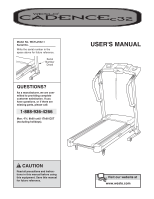
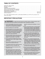
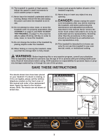
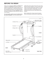
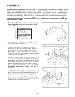
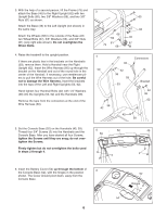
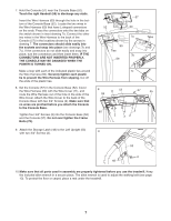
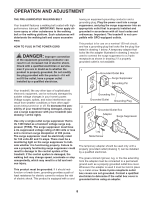
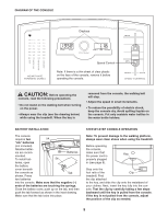
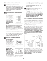
ASSEMBLY Assembly requires two persons. Set the treadmill in a cleared area and remove all packing materials; do not dispose of the packing materials until assembly is completed. Note: The underside of the treadmill walking belt is coated with high-performance lubricant. During shipping, a small amount of lubricant may be transferred to the top of the walking belt or the shipping carton. This does not affect treadmill performance. If there is lubricant on top of the walking belt, simply wipe off the lubricant with a soft cloth and a mild, non-abrasive cleaner. Assembly requires a phillips screwdriver needlenose pliers . , two adjustable wrenches , and 1. Note: To identify small parts used during assembly, refer to the PART IDENTIFICATION CHART in the 1 center of this manual. 46 Attach four Base Pads (63) to the bottom of the Base (46) with four 3/4" Tek Screws (3). 191291 2. Hold an Frame Spacer (27) against one side of the Frame (79) as shown. Insert a Frame Bolt (70) into the frame bolt hole in the Upright Spacer and the Frame. Next, tighten a Spacer Screw (89) into the Upright Spacer and the Frame. Remove the Frame Bolt. Repeat on the other side of the Frame. Identify the Left Upright (53), which does not have a large round hole near the lower end. Hold the Left Upright so the indicated small hole is in the position shown. Loosely thread a Frame Bolt (70) with a Washer (66) and a Star Washer (29) through the Left Upright and the Frame Spacer (27) into the Frame (79) as shown. Do not tighten the bolts used in steps 2 through 5 until step 5 is completed. Hold the Right Upright (62) so the indicated large hole is in the position shown. Insert the Wire Harness (60) into the large hole and out of the top of the Right Upright. Loosely thread a Frame Bolt (70) with a Washer (66) and a Star Washer (2) through the Right Upright (62) and the Frame Spacer (27) into the Frame (79). 63 3 63 3 2a 53 Frame Bolt Hole 79 89 29 27 66 70 Small Hole 2b 27 79 62 29 66 60 Large 70 Hole 5
-
 1
1 -
 2
2 -
 3
3 -
 4
4 -
 5
5 -
 6
6 -
 7
7 -
 8
8 -
 9
9 -
 10
10 -
 11
11 -
12
-
13
-
14
-
15
-
16
-
17
-
18
-
19
 |
 |