Weslo Cadence Dx15 English Manual - Page 5
Assembly
 |
View all Weslo Cadence Dx15 manuals
Add to My Manuals
Save this manual to your list of manuals |
Page 5 highlights
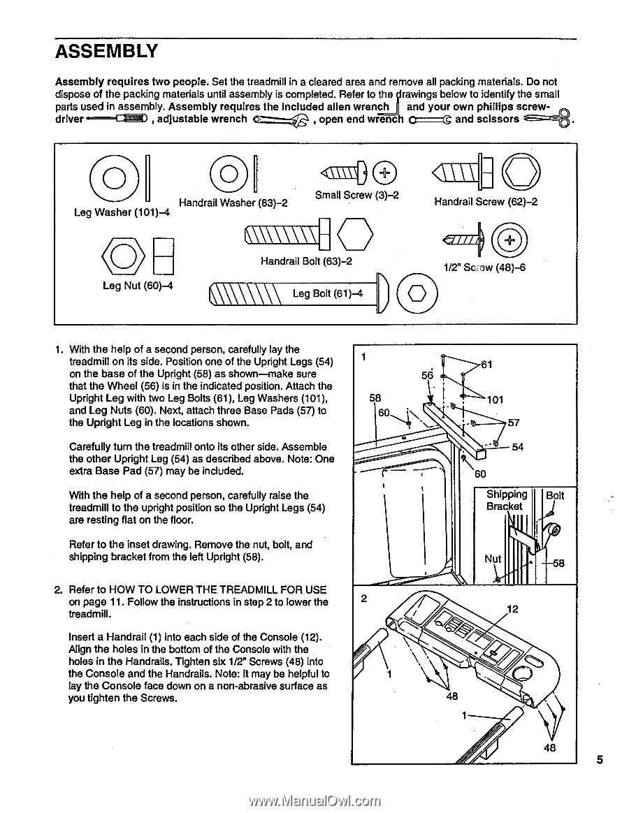
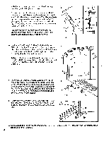
ASSEMBLY Assembly requires two people. Set the treadmill in a cleared area and remove all packing materials. Do not dispose of the packing materials until assembly is completed. Refer to the rawings below to identify the small parts used in assembly. Assembly requires the Included alien wrench and your own phillips screwdriver.----- r= , adjustable wrench €5:===e , open end wrench 0 - --0 and scissors O Handrail Washer (83)-2 Leg Washer (101)-4 0 Small Screw (3)-2 0 \\\\\\\\-- Handrail Bolt (63)-2 Leg Nut (60)-4 V\\\\\\ Leg Bolt (61)-4 0 Handrail Screw (62)-2 44i/// 1/2" Screw (48)-6 1. With the help of a second person, carefully lay the treadmill on its side. Position one of the Upright Legs (54) on the base of the Upright (58) as shown-make sure that the Wheel (56) is in the indicated position. Attach the Upright Leg with two Leg Bolts (61), Leg Washers (101), and Leg Nuts (60). Next, attach three Base Pads (57) to the Upright Leg in the locations shown. Carefully turn the treadmill onto its other side. Assemble the other Upright Leg (54) as described above. Note: One extra Base Pad (57) may be included. With the help of a second person, carefully raise the treadmill to the upright position so the Upright Legs (54) are resting flat on the floor. Refer to the inset drawing. Remove the nut, bolt, and shipping bracket from the left Upright (58). 1 58 60 2. Refer to HOW TO LOWER THE TREADMILL FOR USE on page 11. Follow the instructions in step 2 to lower the 2 treadmill. Insert a Handrail (1) into each side of the Console (12). Align the holes in the bottom of the Console with the holes in the Handrails. Tighten six 1/2" Screws (48) into the Console and the Handrails. Note: It may be helpful to lay the Console face down on a non-abrasive surface as you tighten the Screws. 61 56 101 57 54 60 Shipping Bolt Bracket Nut 8 12 48 1 48 5
-
 1
1 -
 2
2 -
 3
3 -
 4
4 -
 5
5 -
 6
6 -
 7
7 -
 8
8 -
 9
9 -
 10
10 -
 11
11 -
12
-
13
-
14
-
15
-
16
-
17
-
18
-
19
 |
 |