Weslo Cadence G 3.9 Instruction Manual - Page 7
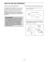
Make sure that the power cord is unplugged.
 |
View all Weslo Cadence G 3.9 manuals
Add to My Manuals
Save this manual to your list of manuals |
Page 7 highlights
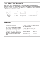
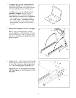
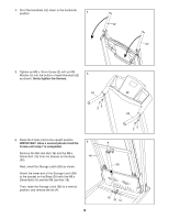
1. To register your product and activate your warranty in the UK, go to iconsupport.eu. If 1 you do not have internet access, call Customer Service (see the front cover of this manual). To register your product and activate your warranty in Australia, email or post the following information to the email address or postal address on the front cover of this manual. • your receipt (make sure to keep a copy) • your name, address, and telephone number • the model number, serial number, and name of your product (see the front cover of this manual) 2. Make sure that the power cord is unplugged. 2 With the help of a second person, carefully raise the Right and Left Uprights (56, 57) to the vertical position. Then, slide the Uprights down onto the top of the Base (35). Make sure not to pinch any wires. 57 56 3. Tighten two M8 x 20mm Screws (2) with two M8 Washers (5) and an M10 x 42mm Screw (1) into 3 the Base (35) and into the Right Upright (56) as shown; do not fully tighten the Screws yet. Repeat this step on the left side of the treadmill. Then, tighten all four Screws (1, 2, 6) on each side. 35 56 5 2 1 6 35 7
-
 1
1 -
 2
2 -
 3
3 -
 4
4 -
 5
5 -
 6
6 -
 7
7 -
 8
8 -
 9
9 -
 10
10 -
 11
11 -
 12
12 -
13
-
14
-
15
-
16
-
17
-
18
-
19
-
20
-
21
-
22
-
23
-
24
 |
 |
