Weslo Flex 505 English Manual - Page 4
Assembly
 |
View all Weslo Flex 505 manuals
Add to My Manuals
Save this manual to your list of manuals |
Page 4 highlights
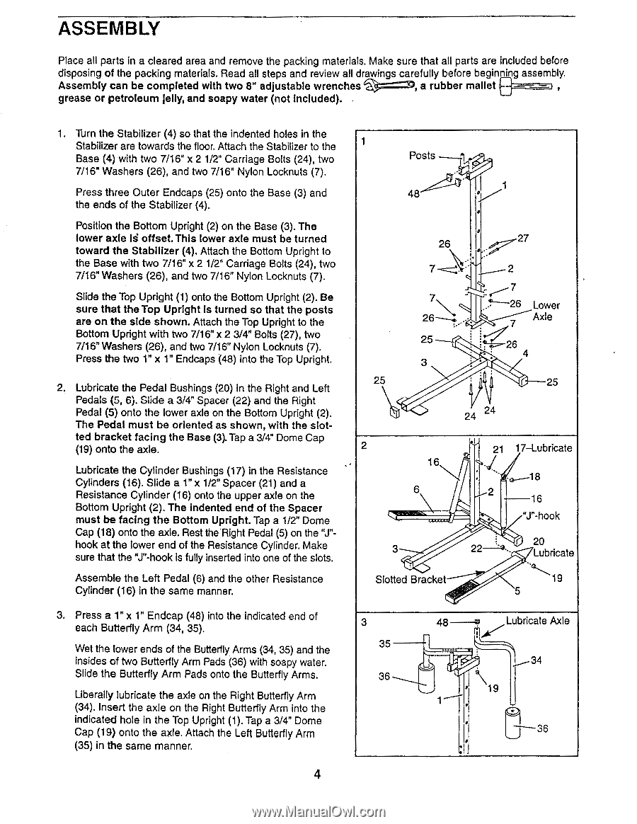
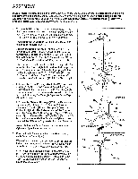
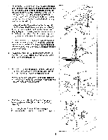
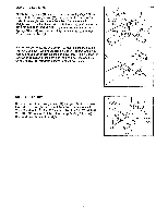
ASSEMBLY Place all parts in a cleared area and remove the packing materials. Make sure that all parts are included before disposing of the packing materials. Read all steps and review all drawings carefully before beginn'ng assembly. Assembly can be completed with two 8" adjustable wrenches =:D, a rubber mallet grease or petroleum jelly, and soapy water (not included). 1. Turn the Stabilizer (4) so that the indented holes in the Stabilizer are towards the floor. Attach the Stabilizer to the Base (4) with two 7/16" x 2 1/2" Carriage Bolts (24), two 7/16" Washers (26), and two 7/16" Nylon Locknuts (7). Press three Outer Endcaps (25) onto the Base (3) and the ends of the Stabilizer (4). Position the Bottom Upright (2) on the Base (3). The lower axle is offset.This lower axle must be turned toward the Stabilizer (4). Attach the Bottom Upright to the Base with two 7/16" x 2 1/2" Carriage Bolts (24), two 7/16" Washers (26), and two 7/16" Nylon Locknuts (7). Slide the Top Upright (1) onto the Bottom Upright (2). Be sure that the Top Upright is turned so that the posts are on the side shown. Attach the Top Upright to the Bottom Upright with two 7/16" x 2 3/4" Bolts (27), two 7/16" Washers (26), and two 7/16" Nylon Locknuts (7). Press the two 1" x 1" Endcaps (48) into the Top Upright. 2. Lubricate the Pedal Bushings (20) in the Right and Left Pedals (5, 6). Slide a 3/4" Spacer (22) and the Right Pedal (5) onto the lower axle on the Bottom Upright (2). The Pedal must be oriented as shown, with the slotted bracket facing the Base (3). Tap a 3/4" Dome Cap (19) onto the axle. Lubricate the Cylinder Bushings (17) in the Resistance Cylinders (16). Slide a 1" x 1/2" Spacer (21) and a Resistance Cylinder (16) onto the upper axle on the Bottom Upright (2). The indented end of the Spacer must be facing the Bottom Upright. Tap a 1/2" Dome Cap (18) onto the axle. Rest the Right Pedal (5) on the "J"hook at the lower end of the Resistance Cylinder. Make sure that the "J"-hook is fully inserted into one of the slots. Assemble the Left Pedal (6) and the other Resistance Cylinder (16) in the same manner. 3. Press a 1" x 1" Endcap (48) into the indicated end of each Butterfly Arm (34, 35). Wet the lower ends of the Butterfly Arms (34, 35) and the insides of two Butterfly Arm Pads (36) with soapy water. Slide the Butterfly Arm Pads onto the Butterfly Arms. Liberally lubricate the axle on the Right Butterfly Arm (34). Insert the axle on the Right Butterfly Arm into the indicated hole in the Top Upright (1). Tap a 3/4" Dome Cap (19) onto the axle. Attach the Left Butterfly Arm (35) in the same manner. 4 1 Posts 1 48 01 26 27 77 25 3 25 2 7 f - -26 7 Lower Axle is 4 -25 24 4 2 16 6 3 Slotted Bracket 21 17-Lubricate 18 2 16 "J"-hook 20 Lubricate 19 5 3 35 36 48 Lubricate Axle ril - 34 19 36
-
 1
1 -
 2
2 -
 3
3 -
 4
4 -
 5
5 -
 6
6 -
 7
7 -
 8
8 -
 9
9 -
 10
10 -
11
-
12
 |
 |