Weslo Pursuit 102 Uk Manual - Page 5
avoid pinching
 |
View all Weslo Pursuit 102 manuals
Add to My Manuals
Save this manual to your list of manuals |
Page 5 highlights
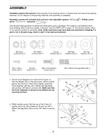
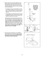
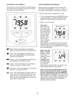
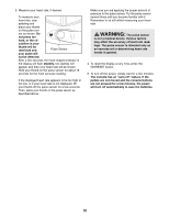
3. Whilst another person holds the Upright (13) in the position shown, connect the Upper Wire (36) to the Reed Switch Wire (43). Cut and remove the zip tie holding the Reed Switch Wire to the Frame (1). Next, connect the Resistance Cable (19) to the Lower Cable (45) in the following way: • See drawing A. Press the small cylinder on the end of the Resistance Cable (19) into the hole in the connector on the Lower Cable (45). Pull the Resistance Cable up and slide it into the slot in the top of the connector. • See drawing B. Turn the Resistance Cable (19) until it is aligned with the slot in the connector, and press the Resistance Cable down into the connector. The Resistance Cable will lock into place. Carefully pull the excess Upper Wire (36) out of the top of the Upright (13), push the excess Cable (19, 45) down into the Frame (1), and insert the Upright into the Frame. Be careful to avoid pinching the Wires and Cables. Next, align one of the adjustment holes in the Upright with the indicated hole in the Frame. Insert the Adjustment Knob (9) into the Frame and the Upright, and turn the Knob clockwise until it is tight. Make sure that the Knob is inserted through one of the adjustment holes in the Upright. 4. The Console (16) requires three 1.5V AA batteries; alkaline batteries are recommended. Insert three batteries into the battery compartment. Make sure that the batteries are oriented as shown by the markings inside the battery compartment. 3 19 45 1 Be careful to avoid pinching the wires and cables whilst inserting the Upright. 13 Adjustment Holes 36 43 Zip Tie Hole 9 A Connector B 19 Hole 45 4 Cylinder Batteries 19 Slot Connector 16 5
-
 1
1 -
 2
2 -
 3
3 -
 4
4 -
 5
5 -
 6
6 -
 7
7 -
 8
8 -
 9
9 -
 10
10 -
 11
11 -
12
-
13
-
14
-
15
-
16
 |
 |
