Weslo Pursuit 350 Bike English Manual - Page 6
See drawing B
 |
View all Weslo Pursuit 350 Bike manuals
Add to My Manuals
Save this manual to your list of manuals |
Page 6 highlights
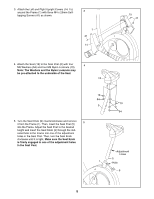
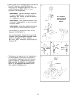
6. While another person holds the Upright (13) near the Frame (1) as shown, connect the Extension Wire (52) to the Reed Switch Wire (43). Next, connect the Resistance Cable (19) to the Lower Cable (45) in the following way: • See drawing A. Pull up on the metal bracket on the Lower Cable (45), and insert the tip of the Resistance Cable (19) into the wire clip inside of the metal bracket as shown. • See drawing B. Firmly pull the Resistance Cable (19) upward and slide it into the top of the metal bracket as shown. • See drawing C. Using pliers, squeeze the prongs on the upper end of the metal bracket together. Push the Wires (52, 43) and the Cables (19, 45) downward into the Frame (1). Next, insert the Upright (13) into the Frame (1). Be careful to avoid pinching the wires and cables. Attach the Upright to the Frame with three M8 x 20mm Button Screws (34) and three M8 Split Washers (42). 6 13 19 45 34 42 A Be careful to avoid pinching the wires and cables. 52 43 42 34 1 B C 7. The Console (16) requires four "AA" batteries (not included); alkaline batteries are recommended. Press the tab on the battery cover and remove it. Insert four batteries into the Console as shown. Make sure that the batteries are oriented as shown by the diagram on the battery cover. Then, reattach the battery cover. Metal Bracket 19 45 7 Metal 19 Bracket 45 Battery Cover Batteries 16 6
-
 1
1 -
 2
2 -
 3
3 -
 4
4 -
 5
5 -
 6
6 -
 7
7 -
 8
8 -
 9
9 -
 10
10 -
 11
11 -
 12
12 -
13
-
14
-
15
-
16
 |
 |
