Weslo Pursuit 895i Bike User Manual - Page 6
Assembly
 |
View all Weslo Pursuit 895i Bike manuals
Add to My Manuals
Save this manual to your list of manuals |
Page 6 highlights
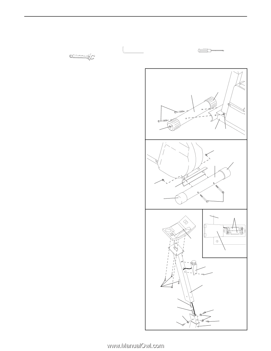
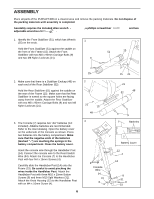
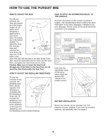
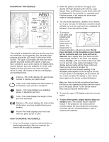
ASSEMBLY Place all parts of the PURSUIT 895i in a cleared area and remove the packing materials. Do not dispose of the packing materials until assembly is completed. Assembly requires the included allen wrench adjustable wrenches . , a phillips screwdriver and two 1. Identify the Front Stabilizer (51), which has Wheels (25) on the ends. Hold the Front Stabilizer (51) against the saddle on the front of the Frame (15). Attach the Front Stabilizer with two M8 x 90mm Carriage Bolts (9) and two M8 Nylon Locknuts (21). 1 9 51 25 2. Make sure that there is a Stabilizer Endcap (48) on each end of the Rear Stabilizer (52). Hold the Rear Stabilizer (61) against the saddle on the rear of the Frame (15). Make sure that the Rear Stabilizer is turned so the square holes are facing away from the saddle. Attach the Rear Stabilizer with two M8 x 90mm Carriage Bolts (9) and two M8 Nylon Locknuts (21). 3. The Console (7) requires two "AA" batteries (not included). Alkaline batteries are recommended. Refer to the inset drawing. Open the battery cover on the underside of the Console as shown. Press two batteries into the battery compartment. Make sure that the negative ends of the batteries (marked "-") are touching the springs in the battery compartment. Close the battery cover. Insert the console wire through the Handlebar Post (14). Connect the console wire to the Reed Switch Wire (54). Attach the Console (7) to the Handlebar Post with four M4 x 16mm Screws (4). Carefully slide the Handlebar Post (14) onto the Frame (15). Be careful to avoid pinching the wires inside the Handlebar Post. Attach the Handlebar Post with three M10 x 25mm Button Screws (8) and three M10 Split Washers (31). Attach the Knob Housing (12) to the Handlebar Post with an M4 x 16mm Screw (4). 6 25 2 21 15 48 3 15 21 21 48 52 9 7 Batteries 7 Battery Cover 4 Console Wire 54 31 8 12 4 14 8 31 8 15
-
 1
1 -
 2
2 -
 3
3 -
 4
4 -
 5
5 -
 6
6 -
 7
7 -
 8
8 -
 9
9 -
 10
10 -
 11
11 -
 12
12 -
13
-
14
-
15
-
16
-
17
-
18
 |
 |