Weslo Pursuit 895i User Manual - Page 5
Maintenance And Trouble-shooting, Part Identification Chart
 |
View all Weslo Pursuit 895i manuals
Add to My Manuals
Save this manual to your list of manuals |
Page 5 highlights
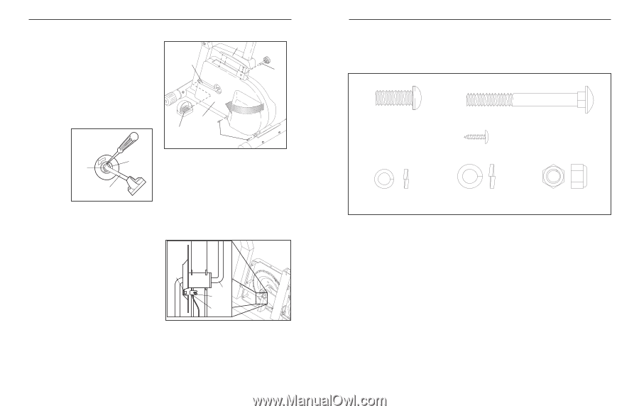
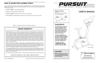
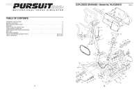
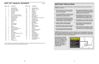
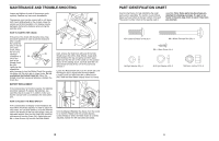
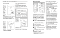
MAINTENANCE AND TROUBLE-SHOOTING Inspect and tighten all parts of the exercise cycle regularly. Replace any worn parts immediately. The exercise cycle can be cleaned with a soft, damp cloth. Avoid spilling liquid on the console. Keep the console out of direct sunlight or the display may be damaged. Remove the batteries when storing the exercise cycle. HOW TO TIGHTEN THE CRANK If the arms of the Crank (33) become loose, they should be tightened in order to prevent excessive wear. Loosen the Crank Nut (56) on the left arm of the Crank. Place the end of a standard 58 screwdriver in 56 one of the slots in the Slotted Crank 33 Nut (58). Lightly tap the screwdriver with a hammer to turn the Slotted Crank Nut counter- clockwise until the arms are no longer loose. Do not overtighten the Slotted Crank Nut. When the Slotted Crank Nut is properly tightened, retighten the Crank Nut. BATTERY REPLACEMENT If the console does not function properly, the batteries should be replaced. To replace the batteries, see assembly step 3 on page 6. In addition, make sure that the console wire is connected to the reed switch wire. HOW TO ADJUST THE REED SWITCH If the console does not display correct feedback, the reed switch should be adjusted. In order to adjust the reed switch, the Left Side Shield (1) must be removed (refer to the drawing at the top of this page). Using an adjustable wrench, turn the Left Pedal (28) clockwise and remove it from the Crank (33). Remove the two M4 x 16mm Screws (4) from the Left Side Shield. 64 33 29 1 28 4 Next, remove the Seat Knob (29) and lift the Side Shield Cover (64) off the Side Shields. Grasp both Side Shields at the top and gently pull them apart. Make sure that the arm of the Crank is in the position shown in the drawing above. Carefully slide the Left Side Shield forward off the arm of the Crank and remove it. Locate the Reed Switch (54). Turn the Crank (33) until the Magnet (55) is aligned with the Reed Switch. Loosen but do not remove the M4 x 16mm Screw (45). Slide the Reed Switch slightly closer to or away 55 33 45 54 from the Magnet. Retighten the Screw. Turn the Crank for a moment. Repeat until the console displays correct feedback. When the Reed Switch is correctly adjusted, reattach the left side shield and pedal. 12 PART IDENTIFICATION CHART Use the chart below for help identifying the small parts used in assembly. The number in parenthesis below each part refers to the key number of the part. The second number refers to the quantity used in assembly. Note: Some parts may have been preattached for shipping purposes. If a part is not found in the parts bag, check to see if it has been pre-attached. M10 x 25mm Button Screw (8)Ð5 M8 x 80mm Carriage Bolt (30)Ð4 M4 x 16mm Screw (4)Ð4 M8 Split Washer (53)Ð4 M10 Split Washer (63)Ð5 M8 Nylon Locknut (21)Ð8 5
-
 1
1 -
 2
2 -
 3
3 -
 4
4 -
 5
5 -
 6
6 -
 7
7 -
 8
8
 |
 |