Whirlpool CEM2940TQ Installation Instructions - Page 15
Connect Vent, Complete Installation - coin operated electric dryer
 |
View all Whirlpool CEM2940TQ manuals
Add to My Manuals
Save this manual to your list of manuals |
Page 15 highlights
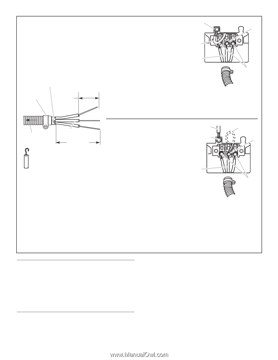
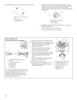
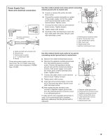
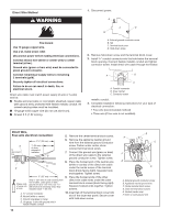
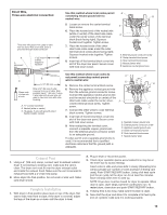
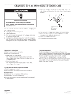
Direct Wire, Three-wire electrical connection: Three wire with ground wire: green or bare wire cut short. Wire is not used. Dryer is grounded through neutral conductor. A to disconnect box 1" (25 mm) of wires stripped of insulation Use this method where local codes permit connecting neutral ground wire to neutral wire: 5. Loosen or remove the center terminal block screw. 6. Place the hooked end of the neutral wire (white or center) of the direct wire cable under the center screw of the terminal block (hook facing right). Squeeze hooked end together. Tighten screw. 7. Place the hooked ends of the other direct wire cable wires under the outer terminal block screws (hook facing right). Squeeze hooked ends together. Tighten screws. 8. Insert tab of the terminal block cover into slot of the dryer rear panel. Secure cover with hold-down screw. A B E D C A. External ground conductor screw B. Center terminal block screw C. Outer terminal block screws D. Neutral (center wire) E. Appliance neutral ground wire C Shape ends of wires into a hook. B 3-1/2" (89 mm) Strip 3-1⁄2" (89 mm) of outer covering from end of cable. Strip insulation back 1" (25 mm). If using 3 wire cable with ground wire, cut green or bare wire even with outer covering. A. 3/4" conduit connector B. Neutral (white or center) C. 10-gauge, 3 wire with ground wire in flexible metallic conduit Use this method where local codes do not permit connecting neutral ground wire to neutral wire: 5. Remove the center terminal block screw. 6. Remove the appliance neutral ground wire from the external ground conductor screw. Connect the appliance neutral ground wire and the neutral wire (white or center) of the direct wire cable under the center, silvercolored terminal block screw. Tighten screw. 7. Connect the other wires to outer terminal block screws. Tighten screws. 8. Insert tab of the terminal block cover into slot of the dryer rear panel. Secure cover with hold-down screw. 9. After reattaching the terminal cover, connect a separate copper ground wire from the external ground connector screw to an adequate ground. If codes permit and a separate ground wire is used, it is recommended that a qualified electrician determine that the ground path is adequate. A C B D F E A. Separate copper ground wire B. External ground conductor screw C. Appliance neutral ground wire D. Center terminal block screw E. Outer terminal block screws F. Neutral (center wire) Connect Vent 1. Using a 4" (102 mm) clamp, connect vent to exhaust outlet in dryer. If connecting to existing vent, make sure the vent is clean. The dryer vent must fit over the dryer exhaust outlet and inside the exhaust hood. Make sure the vent is secured to exhaust hood with a 4" (102 mm) clamp. 2. Move dryer into final position. Do not crush or kink vent. Make sure dryer is level. Complete Installation 1. With dryer in final position place level on top of the dryer, first side to side; then front to back. If the dryer is not level, adjust the legs of the dryer up or down until the dryer is level. 2. Plug in dryer or reconnect power. 3. Check dryer operation (some accumulated time may be on the timer due to factory testing). Insert coins in slide and press slide in slowly. (Operating time will accumulate per number of coins and type of timing cam used.) Push START/RESTART button. Using a full heat cycle (not the air cycle), let the dryer run for at least five minutes. Dryer will stop when time is used up. NOTE: Dryer door must be closed for dryer to operate. When door is open, dryer stops, but timer continues to run. To restart dryer, close door and push START/RESTART button. 4. If drying time is too long, make sure lint screen is clean. 5. Now start the dryer and allow it to complete a full heat cycle (not air cycle) to make sure it is working properly. 15
-
 1
1 -
2
-
3
-
4
-
5
-
6
-
7
-
8
-
9
-
 10
10 -
 11
11 -
 12
12 -
 13
13 -
 14
14 -
 15
15 -
 16
16
 |
 |