Whirlpool CEM2940TQ Installation Instructions - Page 9
Multiple Dryer Venting - capacity
 |
View all Whirlpool CEM2940TQ manuals
Add to My Manuals
Save this manual to your list of manuals |
Page 9 highlights
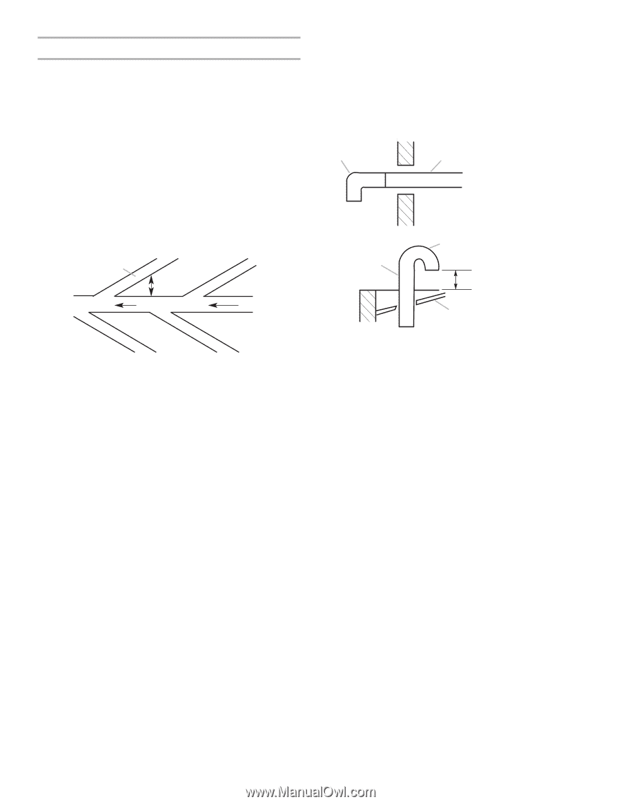
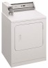
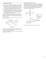
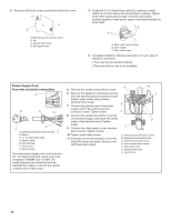
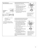
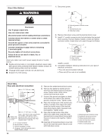
Multiple Dryer Venting I A main vent can be used for venting a group of dryers. Main vent should be sized to remove 200 CFM of air per dryer. Large-capacity lint screens of proper design may be used in the main vent if checked and cleaned frequently. The room where the dryers are located should have make-up air equal to or greater than the CFM of all the dryers in the room. I Back-draft Damper Kits, Part No. 3391910, are available from your Whirlpool dealer and should be installed in each dryer's vent to prevent exhausted air from returning into the dryers and to keep the exhaust in balance within the main vent. Unobstructed air openings are required. Each vent should enter the main vent at an angle pointing in the direction of the airflow. Vents entering from the opposite side should be staggered to reduce the exhausted air from interfering with the other vents. The maximum angle of each vent entering the main vent should be no more than 30°. A air flow 30° max. B If an exhaust hood cannot be used: The outside end of the main vent should have a sweep elbow directed downward. If the main vent travels vertically through the roof, rather than through the wall, install a 180° sweep elbow on the end of the vent at least 2 feet (610 mm) above the highest part of the building. The opening wall or roof shall have a diameter 1/2" (13 mm) larger than the vent diameter. The vent should be centered in the opening. B A C D C F A. Exhaust hood or elbow B. Wall C. Main collector vent D. Horizontal vent E E. 180° sweep elbow F. Vertical vent G. Roof 2 ft. (610 mm) min. above highest point of building G A. Individual dryer vent B. Main vent Keep air openings free of dry cleaning fluid fumes. Fumes create acids which, when drawn through the dryer heating units, can damage dryers and loads being dried. A clean-out cover should be located on the main vent for periodic cleaning of the vent system. Do not install screening or cap over the end of the vent. 9
-
 1
1 -
2
-
3
-
 4
4 -
 5
5 -
 6
6 -
 7
7 -
 8
8 -
 9
9 -
 10
10 -
 11
11 -
 12
12 -
 13
13 -
 14
14 -
15
-
16
 |
 |