Whirlpool LTE5243DQ Installation Instructions - Page 8
wire connection: Power supply cord, Use where local codes permit connecting cabinet-ground,
 |
UPC - 050946532578
View all Whirlpool LTE5243DQ manuals
Add to My Manuals
Save this manual to your list of manuals |
Page 8 highlights
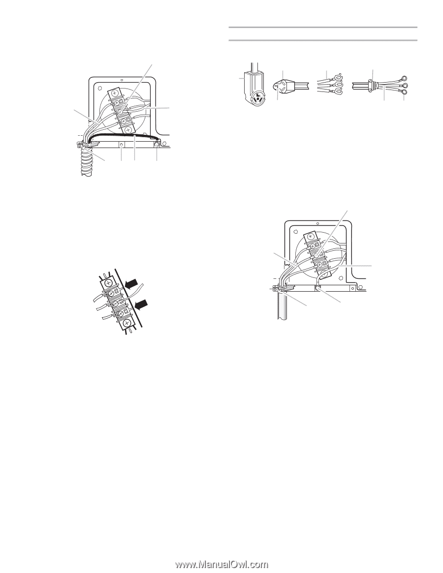
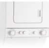
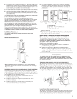
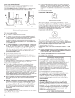
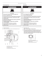
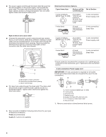
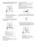
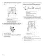
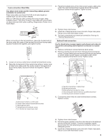
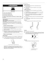
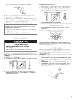
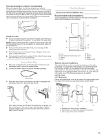
3. Move the green painted screw from the internal to the external ground location. Connect ground wire (green or bare) of power supply cable to external ground conductor screw. Tighten screw. B 3-wire connection: Power supply cord Use where local codes permit connecting cabinet-ground conductor to neutral wire. B D E A A C G FE D A. Neutral wire (white or center wire) B. Center silver-colored terminal block screw C. Neutral ground wire D. External ground conductor screw E. Ground wire (green or bare) of power supply cable F. Internal ground conductor location G. ¾" (19 mm) UL listed strain relief 4. Place the hooked ends of the other power supply cable wires under the outer terminal block screws (hooks facing right). Squeeze hooked ends together. Tighten screws. C GF A. 3-wire receptacle (NEMA type 10-30R) B. 3-wire plug C. Neutral prong D. Spade terminals with upturned ends E. 3⁄4" (19 mm) UL listed strain relief F. Ring terminals G. Neutral (white or center wire) 1. Loosen or remove center silver-colored terminal block screw. 2. Connect neutral wire (white or center wire) of power supply cord to the center silver-colored terminal screw of the terminal block. Tighten screw. B A C E D 5. Tighten strain relief screw. 6. Insert tab of terminal block cover into slot of dryer rear panel. Secure cover with hold-down screw. 7. You have completed your electrical connection. Now go to "Venting Requirements." A. Neutral wire (white or center wire) B. Center silver-colored terminal block screw C. Neutral ground wire D. Internal ground conductor screw E. ¾" (19 mm) UL listed strain relief 3. Connect the other wires to outer terminal block screws. Tighten screws. 4. Tighten strain relief screws. 5. Insert tab of terminal block cover into slot of dryer rear panel. Secure cover with hold-down screw. 6. You have completed your electrical connection. Now go to "Venting Requirements." 8
-
 1
1 -
2
-
 3
3 -
 4
4 -
 5
5 -
 6
6 -
 7
7 -
 8
8 -
 9
9 -
 10
10 -
 11
11 -
 12
12 -
 13
13 -
14
-
15
-
16
 |
 |