Whirlpool RC8700EDB Installation Instructions - Page 2
Before You Start..., Tools And Materials Needed, Parts Supplied, Cutout Dimensions - model
 |
UPC - 050946528762
View all Whirlpool RC8700EDB manuals
Add to My Manuals
Save this manual to your list of manuals |
Page 2 highlights
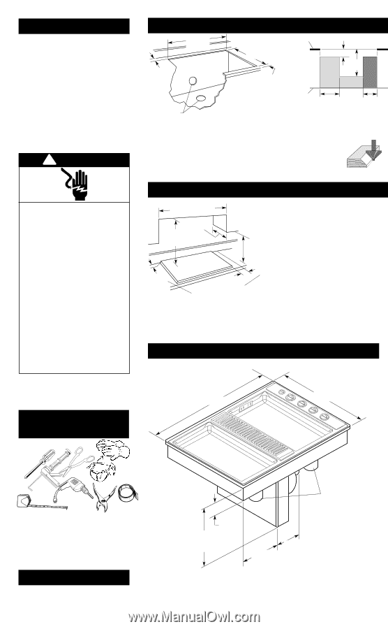
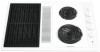
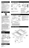
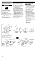
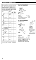
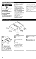
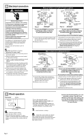
Before you start... Important: Observe all governing codes and ordinances. Proper installation is your responsibility. • Make sure you have everything necessary for correct installation. • Have a qualified technician install this cooktop. • Comply with the installation clearances specified on the model/serial rating plate. Model/serial rating plate is located on the left side of the downdraft plenum. Cooktop location should be away from strong draft areas, such as windows, doors and strong heating vents or fans. Locate cooktop for convenient use in kitchen. Grounded electrical system is required. See "Electrical requirements," Page 4. Venting duct must terminate outdoors. All openings in the wall or floor where cooktop is to be installed must be sealed. ! WARNING Electrical Shock Hazard It is the customer's responsibility to contact a qualified electrical installer, to make sure that the electrical installation is correct, and to make sure the electrical installation follows the National Electrical Code, ANSI/NFPA 70 - latest edition*, and all local codes and ordinances. Take special care when cutting holes into a wall. Electrical wires may be behind the wall covering and could cause an electrical shock if you touch them. Disconnect the power to any electrical circuits that could be affected by the installation of this product. Failure to do so could result in death or serious injury. Injury Hazard To eliminate the risk of burns or fires, Do Not install cabinets or store things above the cooktop. If cabinets are already installed above the cooktop, install a range hood to the bottom of the cabinet to prevent reaching over a heated cooking surface. The range hood should stick out a minimum of 5 inches (12.7 cm) from the front of the cabinets. Reaching over a heated cooking surface could result in a serious burn or other injury. This appliance is Not approved for use in mobile homes. *Copies of the standards listed may be obtained from: National Fire Protection Association Batterymarch Park Quincy, Massachusetts 02269 Tools and materials needed: Cutout dimensions 28-7/8" (73.3 cm) cutout width 15/16" (2.4 cm) minimum distance to backsplash or vertical wall Select required duct cutout (see Page 2 for exhaust duct cutout location). Countertop must be supported within 3" (7.6 cm) of cutout. countertop 20-7/8" (53.2 cm) cutout depth 1-7/8" (4.8 cm) minimum space to front edge of countertop Install rear wall junction box in shaded area. Darker shaded area is preferred. 5" (12.7 cm) 17" (43.2 cm) floor 11" (27.9 cm) 8" (20.3 cm) Minimum base cabinet dimensions - 30" (76.2 cm) base cabinet 24" (61.0 cm) base cabinet depth 25" (63.5 cm) countertop depth If cabinet has drawers, drawers will need to be removed and drawer fronts installed on front of cabinet. Cutout preparation: Decorative laminate - Chamfer all exposed edges to prevent chipping laminate. Cut radius corners and file to smooth edges and to prevent cracking. Clearance dimensions 30" (76.2 cm) minimum when higher than 18" (45.7 cm) See Note** for minimum clearances. 13" (33 cm) maximum upper cabinet depth Installation location should provide sufficient room for removing grease containers. 18" (45.7 cm) minimum clearance upper cabinet to countertop 3/4" (1.9 cm) Do Not seal cooktop to countertop. 6" both sides (15.2 cm) Minimum distance to nearest combustible vertical surface extending 18" (45.7 cm) above cooktop ** Note: 24" (61.0 cm) minimum when bottom of wood or metal cabinet is protected by not less than 1/4" flame retardant millboard covered with not less than No. 28 MSG sheet steel, 0.015" stainless steel, 0.024" aluminum or 0.020" copper. 30" (76.2 cm) minimum clearance between the top of the cooking platform and bottom of unprotected wood or sheet metal. Side clearance - 6" (15.2 cm) minimum clearance between side of cooktop and side wall is recommended for maximum ventilation performance. Rear clearance - 3/4" (1.9 cm) clearance between rear edge of appliance and rear wall is required. Motor/blower clearance - 2" (5.1 cm) minimum clearance between motor and cabinet is required for proper cooling. 6" (15.2 cm) clearance is recommended for servicing access. Product dimensions 29-7/8" (75.9 cm) width 21-1/2" (54.6 cm) depth Phillips screwdriver gloves metal snips safety glasses caulking gun with weatherproof caulking tape measure hand or electric drill pliers duct tape Not shown: • wall or roof cap • metal ductwork • 2 sheet metal screws to attach transition duct to venting adapter • Two U.L.-listed 1/2" conduit connectors • Flexible, armored or non-metallic sheathed copper cable (with grounding wire) that conforms to existing codes (see "Electrical requirements" Page 4). Length required depends on your installation. • Twist-on connectors. Number and size will depend on your installation. See "Electrical connection," Page 5. Parts supplied: Remove parts from packages. Check that all parts were included. • literature pack • exhaust flow rate tester card Page 1 Blower can be swiveled 90°. Appliance junction box is located under right side of cooktop. grease containers 16-7/16" (41.8 cm) blower housing depth 3-3/4" (9.5 cm) burner box depth 11-7/8" (30.2 cm) 12-7/16" (31.6 cm)
-
 1
1 -
 2
2 -
 3
3 -
 4
4 -
 5
5 -
 6
6 -
 7
7
 |
 |