Whirlpool RC8700EDB Installation Instructions - Page 5
ELECTRICAL REQUIREMENTS, INSTALLATION STEPS, Preparation, Installation, Duct connection - for gas cooktop
 |
UPC - 050946528762
View all Whirlpool RC8700EDB manuals
Add to My Manuals
Save this manual to your list of manuals |
Page 5 highlights
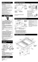
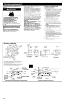
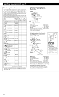
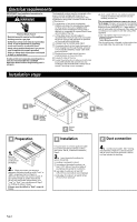
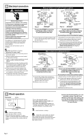
Electrical requirements IMPORTANT: Save Installation Instructions for electrical inspector's use. ! WARNING Electrical Shock Hazard Electrical ground is required on this appliance. Do Not ground to a gas pipe. Do Not have a fuse in the neutral or grounding circuit. A fuse in the neutral or grounding circuit could result in an electrical shock. Check with a qualified electrician if you are not sure the appliance is properly grounded. Failure to follow these instructions could result in death or serious injury. If codes permit and a separate grounding wire is used, it is recommended that a qualified electrician determine that the grounding path is adequate. The downdraft cooktop must be connected to the proper electrical voltage and frequency as specified on the model/serial rating plate. (The model/serial rating plate is located on the left side of the plenum.) ࠜ A three-wire or four-wire, single-phase, 120/240-volt, 60-Hz, AC-only electrical supply (or three-wire or four-wire, 120/208-volt if specified on the model/serial rating plate) is required on a separate 40-ampere circuit, fused on both sides of the line. ࠜ A time-delay fuse or circuit breaker is recommended. The fuse size must not exceed the circuit rating of the appliance as specified on the model/serial rating plate. ࠜ CONNECT WITH COPPER WIRE ONLY. ࠜ Connected directly to the fused disconnect (or circuit breaker box) through flexible, armored or non-metallic sheathed, copper cable (with grounding wire). ࠜ Flexible armored cable should connect cooktop directly to the junction box. ࠜ Fuse both sides of the line. ࠜ Locate the junction box to allow as much slack as possible between the junction box and cooktop so that the downdraft cooktop can be moved if servicing is ever necessary. Installation steps ࠜ A U.L.-listed 1/2" (1.3 cm) conduit connector must be provided at the junction box and cooktop junction box. The recommended minimum copper wire size is No.-8 gauge. However, wire sizes and connections must conform to the requirements of the National Electrical Code, ANSI/NFPA 70 - latest edition*, and all local codes and ordinances. Wire sizes and connections must conform with the rating of the appliance. Copies of the standard listed may be obtained from: * National Fire Protection Association Batterymarch Park Quincy, Massachusetts 02269 The wiring diagram is located on the junction box cover plate under the right side of the unit. Align B cooktop in cutout Check each E element for proper operation A Preparation 1. Remove downdraft cooktop from packaging. 2. Check equivalent duct length to determine if blower should be set at "Low" or "High" range (see chart on Page 3 to determine equivalent duct system length). If duct system length is greater than 30 feet (9.1m), shift the blower range setting from "Low" to "High" (see instructions on Page 3 for shifting the blower range). If blower must be shifted to "High" range, do it now. Check A blower range setting Make D electrical connection Connect C duct system B Installation It may be easier to connect appliance cable to junction box before inserting cooktop into cutout. See D, "Electrical connection," Page 5. 3. Insert downdraft cooktop into cutout. Check that: cooktop is centered in cutout. front edge of downdraft cooktop is at least 1-1/2" (3.8 cm) from front edge of countertop and parallel to countertop. rear edge of cooktop is at least 3/4" (1.9 cm) from rear wall as recommended. side edge of cooktop is at least 6 inches (15.2 cm) from side wall. C Duct connection 4. Connect duct system. See "Venting requirements," Pages 2-3. Use duct tape to seal all joints. Duct must end with a wall or roof cap outside the building. Page 4
-
 1
1 -
 2
2 -
 3
3 -
 4
4 -
 5
5 -
 6
6 -
 7
7
 |
 |
