Whirlpool RC8700EDB Installation Instructions - Page 6
Check operation, Electrical connection - modules
 |
UPC - 050946528762
View all Whirlpool RC8700EDB manuals
Add to My Manuals
Save this manual to your list of manuals |
Page 6 highlights
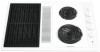
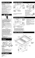
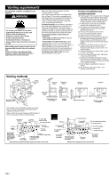
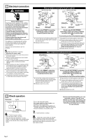
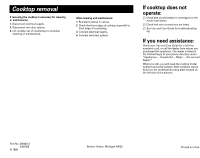
D Electrical connection ! WARNING Electrical Shock Hazard Electrical ground is required on this cooktop. Do Not connect to the electrical supply until the cooktop is permanently grounded. Disconnect power to the junction box before making the electrical connection. This cooktop must be connected to a grounded, metallic, permanent wiring system, or a grounding connector should be connected to the grounding terminal or wire lead on the cooktop. Failure to follow these instructions could result in death or serious injury. This appliance is manufactured with a white (neutral) power supply wire and a cooktopconnected green (or bare) grounding wire twisted together. Appliance cable and connectors are not provided. 5. Make the electrical connection: 1. Disconnect the power supply. 2. Remove the junction box cover from junction box inside cabinet. 3. Remove cooktop junction box cover located on right side of cooktop. 4. Use a U.L.-listed conduit connector to connect appliance cable to junction box inside cabinet. 5. Remove knockout on side of cooktop junction box needed to fit size of appliance cable. Use a U.L.-listed conduit connector to connect appliance cable to cooktop junction box. 6. Connect the two black wires together with twist-on connectors in both junction boxes. 7. Connect the two red wires together with twiston connectors in both junction boxes. 8. Complete the electrical connection according to local codes and ordinances. (See chart.) Wire connections: Junction box in wall or cabinet cable from power supply junction box red wires black wires cable from power supply junction box red wires white wires white wire white and bare grounding appliance cable wires Figure 1 U.L.-listed conduit connector appliance cable from cooktop If local codes PERMIT connecting cooktop-grounding conductor to neutral junction box wire: 9. Connect the bare and white appliance cable wires to the neutral (white) wire in junction box. See Figure 1. 10. Replace junction box cover. green or bare grounding wires Figure 2 appliance cable from cooktop black wires U.L.-listed conduit connector If local codes DO NOT PERMIT connecting cooktop-grounding conductor to neutral white wire in junction box OR If connecting to a four-wire electrical system: 9. Separate bare and white appliance cable wires. 10. Connect white appliance cable wire to neutral (white) wire in junction box. See Figure 2. 11. Connect the bare grounding appliance cable wire to the green grounding wire in junction box. Do Not connect bare grounding wire to neutral (white) wire in junction box. See Figure 2. 12. Replace junction box cover. Wire connections: Cooktop junction box white and green or bare grounding wires white wires red wires red wires Figure 3 black wires If local codes PERMIT connecting cooktop-grounding conductor to neutral junction box wire: 9. Connect the cooktop white and green or bare grounding wire to the neutral (white) wire and bare grounding wire in the appliance cable. See Figure 3. 10. Replace junction box cover. bare or green grounding wires Figure 4 black wires If local codes DO NOT PERMIT connecting cooktop-grounding conductor to neutral white wire in junction box OR If connecting to a four-wire electrical system: 9. Separate bare and white appliance cable wires. 10. Connect white appliance cable wire to neutral (white) wire in junction box. See Figure 4. 11. Connect the bare grounding appliance cable wire to the bare or green grounding wire in junction box. Do Not connect bare grounding wire to neutral (white) wire in junction box. See Figure 4. 12. Replace junction box cover. E Check operation flow tester air intake flow tester edge of line on flow tester front of cooktop 6. Check for proper venting: • Check that the air filter is in place. • Align the dotted line labeled for "cooktop models" on the flow tester with the edge of the intake on the left side of the cooktop near the center. • Turn on the downdraft system: If the card is pulled into the air intake, your downdraft is working properly. If the card is not pulled into the system, see "Venting requirements," Pages 2-3, and check ductwork installation for possible causes. 7. Install modules in cooktop. 8. Check that modules heat and indicator light is operating correctly. If the downdraft cooktop does not operate, disconnect the power supply and check that wire connections have been made correctly. You have just finished installing your new downdraft cooktop. To get the most efficient use from your new cooktop, read your Use & Care Guide. Keep Installation Instructions and Guide close to cooktop for easy reference. Page 5
-
 1
1 -
 2
2 -
 3
3 -
 4
4 -
 5
5 -
 6
6 -
 7
7
 |
 |