Whirlpool UXT4230AYT Use & Care Guide - Page 7
Installation Instructions - appliances
 |
View all Whirlpool UXT4230AYT manuals
Add to My Manuals
Save this manual to your list of manuals |
Page 7 highlights
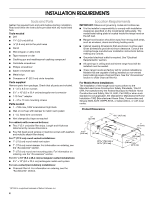
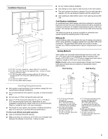
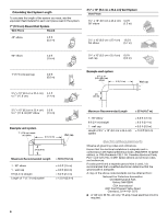
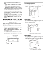
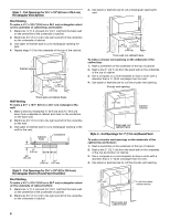
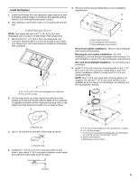
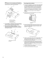
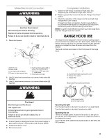
■ If the house has aluminum wiring, follow the procedure below: 1. Connect a section of solid copper wire to the pigtail leads. 2. Connect the aluminum wiring to the added section of copper wire using special connectors and/or tools designed and UL listed for joining copper to aluminum. Follow the electrical connector manufacturer's recommended procedure. Aluminum/copper connection must conform with local codes and industry accepted wiring practices. ■ Wire sizes and connections must conform with the rating of the appliance as specified on the model/serial rating plate. The model/serial plate is located behind the filter on the rear wall of the range hood. ■ Wire sizes must conform to the requirements of the National Electrical Code, ANSI/NFPA 70 (latest edition), or CSA Standards C22. 1-94, Canadian Electrical Code, Part 1 and C22.2 No. 0-M91 (latest edition) and all local codes and ordinances. INSTALLATION INSTRUCTIONS Prepare Location NOTE: It is recommended that the vent system be installed before hood is installed. Before making cutouts, make sure there is proper clearance within the ceiling or wall for exhaust vent. 1. Disconnect power. 2. Depending on your model, determine which venting method to use: roof, wall or non-vented (recirculating). 3. Select a flat surface for assembling the range hood. Place covering over that surface. 4. Lift the range hood and set it upside down onto covered surface. 5. If cabinet has recessed bottom, add wood filler strips on each side. Install screws to attach filler strips in locations shown. 3" (7.6 cm) Wood filler strips (recessed cabinet bottoms only) Cabinet bottom Determine Wiring Hole Location Cut only one 1¹⁄₄" (3.2 cm) diameter wiring access hole. 1. Determine and clearly mark a vertical centerline on the wall and cabinet in the area the vent opening will be made. A A. Centerline To wire through top: 1. Mark a line distance "A" from the right of the centerline on the underside of the cabinet. Mark the point on this line that is 2.2 cm) from back wall. Drill a 1¼" (3.2 cm) diameter hole through the cabinet at this point. A ⁷⁄₈" (2.2 cm) from wall, not cabinet frame Centerline A. 8³⁄₈" (21.3 cm) for 30" (76.2 cm) models 11³⁄₈" (28.9 cm) for 36" (91.4 cm) models To wire through wall: 1. Mark a line distance "A" from the right of the centerline on the underside of the wall. Mark the point on this line that is 2.2 cm) from the underside of the cabinet. Drill a 1¹⁄₄" (3.2 cm) diameter hole through the rear wall at this point. 3" (7.6 cm) Wall ⁷⁄₈" (2.2 cm) A Centerline A. 8³⁄₈" (21.3 cm) for 30" (76.2 cm) models 11³⁄₈" (28.9 cm) for 36" (91.4 cm) models 7
-
 1
1 -
 2
2 -
 3
3 -
 4
4 -
 5
5 -
 6
6 -
 7
7 -
 8
8 -
 9
9 -
 10
10 -
 11
11 -
 12
12 -
13
-
14
-
15
-
16
-
17
-
18
-
19
-
20
-
21
-
22
-
23
-
24
-
25
-
26
-
27
-
28
-
29
-
30
-
31
-
32
 |
 |
