Whirlpool WEE745H0FS Installation Guide - Page 15
Bare Wire Torque Specifications
 |
View all Whirlpool WEE745H0FS manuals
Add to My Manuals
Save this manual to your list of manuals |
Page 15 highlights
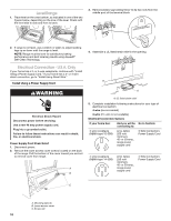
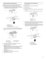
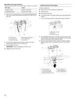
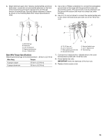
4. Attach terminal lugs to line 1 (black), neutral (white), and line 2 (red) wires. Loosen (do not remove) the setscrew on the front of the terminal lug and insert exposed wire end through bottom of terminal lugs. Securely tighten setscrew to torque as shown in the following Bare Wire Torque Specifications chart. A 5. Use a hex or Phillips screwdriver to connect the bare (green) ground wire to the range with the ground-link screw and ground-link section. The ground wire must be attached over the ground-link section and must not contact any other terminal. 6. Use ³⁄₈" (1.0 cm) nut driver to connect the neutral (white) wire to the center terminal block post with one of the 10-32 hex nuts. G B A C D E B F A. Terminal lug B. Setscrew C. Line 2 (red) wire D. Neutral (white) wire E. Line 1 (black) wire Bare Wire Torque Specifications Attaching terminal lugs to the terminal block - 20 lbs-in. (2.3 N-m) Wire Awg Torque 8 gauge copper 25 lbs-in. (2.8 N-m) 6 gauge aluminum 35 lbs-in. (4.0 N-m) C A. 10-32 hex nut B. Line 2 (red) wire C. Bare (green) ground wire D. Ground-link screw DE E. Neutral (white) wire F. Line 1 (black) wire G. Terminal lug 7. Connect line 2 (red) and line 1 (black) wires to the outer terminal block posts with 10-32 hex nuts. 8. Firmly tighten hex nuts. IMPORTANT: Verify the tightness of the hex nuts. 9. Replace lower access cover. 15
-
 1
1 -
2
-
3
-
4
-
5
-
6
-
7
-
8
-
9
-
 10
10 -
 11
11 -
 12
12 -
 13
13 -
 14
14 -
 15
15 -
 16
16 -
 17
17 -
 18
18 -
 19
19 -
 20
20 -
21
-
22
-
23
-
24
-
25
-
26
-
27
-
28
-
29
-
30
-
31
-
32
 |
 |
