Whirlpool WGD6600VW Use and Care Guide - Page 6
Swarning
 |
UPC - 883049141237
View all Whirlpool WGD6600VW manuals
Add to My Manuals
Save this manual to your list of manuals |
Page 6 highlights
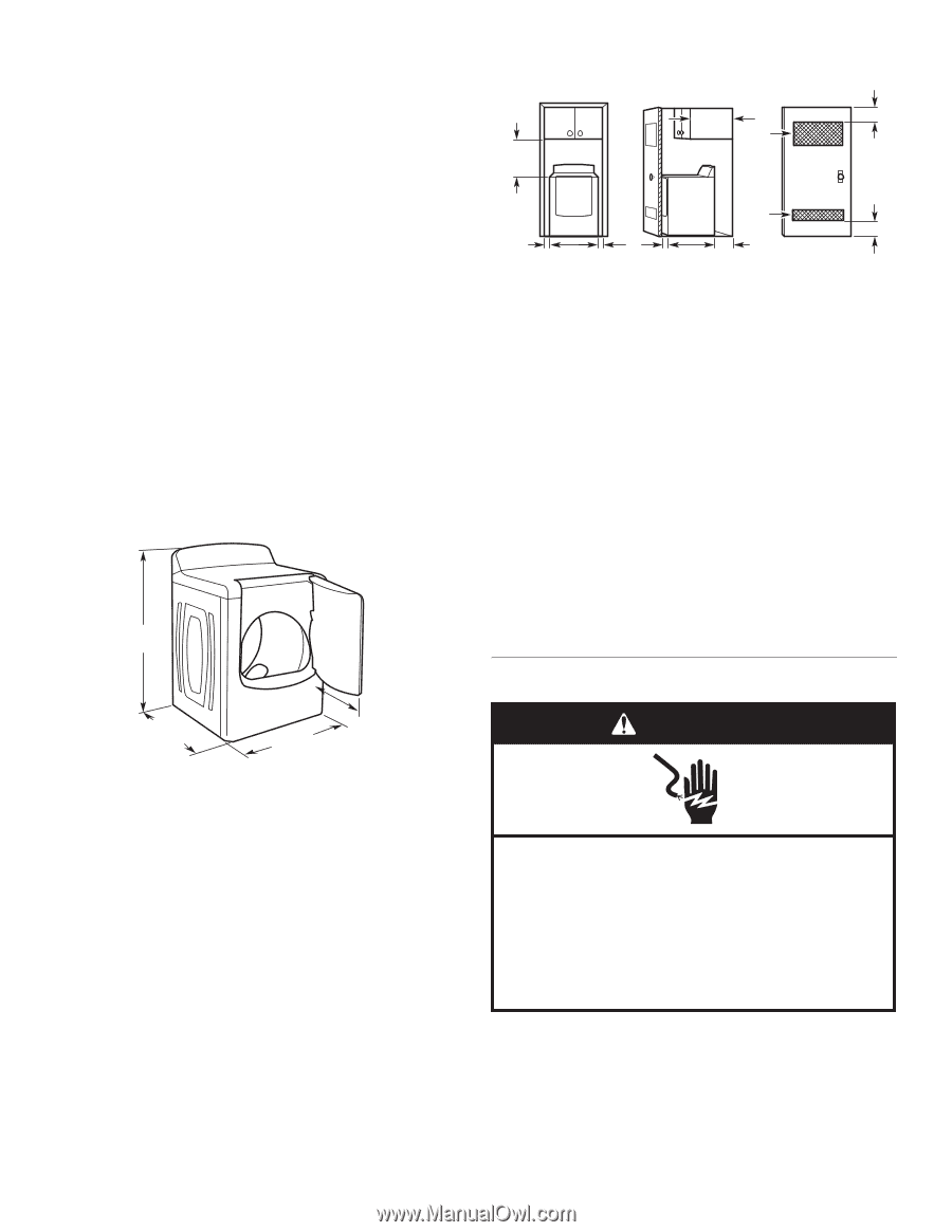
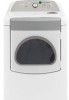
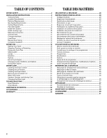
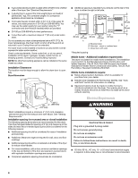
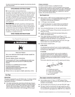
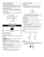
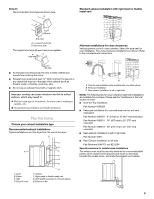
■ A grounded electrical outlet located within 2 ft (610 mm) of either side of the dryer. See "Electrical Requirements." ■ A sturdy floor to support the total weight (dryer and load) of 200 lbs (90.7 kg). The combined weight of a companion appliance should also be considered. ■ Cold water faucets located within 4 ft (1.2 m) of the water fill valves, and water pressure of 20-100 psi (138-690 kPa). You may use the water supply for your washer using the "Y" connector and short hose (if needed) which are provided. ■ 20-100 psi (138-690 kPa) for best performance. ■ A level floor with a maximum slope of 1" (25 mm) under entire dryer. Do not operate your dryer at temperatures below 45ºF (7ºC). At lower temperatures, the dryer might not shut off at the end of an automatic cycle. Drying times can be extended. The dryer must not be installed or stored in an area where it will be exposed to water and/or weather. Check code requirements. Some codes limit, or do not permit, installation of the dryer in garages, closets, mobile homes, or sleeping quarters. Contact your local building inspector. NOTE: No other fuel-burning appliance can be installed in the same closet as a dryer. Installation Clearances The location must be large enough to allow the dryer door to open fully. Dryer Dimensions 431/2" (1105 mm) 291/4" (743 mm) 29" (737 mm) 221/4" (565 mm) *Most installations require a minimum 5" (127 mm) clearance behind the dryer for the exhaust vent with elbow. See "Venting Requirements." Installation spacing for recessed area or closet installation The following spacing dimensions are recommended for this dryer. This dryer has been tested for spacing of 0" (0 mm) clearance on the sides and rear. Recommended spacing should be considered for the following reasons: ■ Additional spacing should be considered for ease of installation and servicing. ■ Additional clearances might be required for wall, door, and floor moldings. ■ Additional spacing should be considered on all sides of the dryer to reduce noise transfer. ■ For closet installation, with a door, minimum ventilation openings in the top and bottom of the door are required. Louvered doors with equivalent ventilation openings are acceptable. ■ Companion appliance spacing should also be considered. ■ Additional spacing is required if you exhaust out the rear of the dryer to either the right or left side. 18"* (457 mm) 14" máx.* (356 mm) 48 in.2* (310 cm2) 24 in.2* (155 cm2) 1" (25 mm) 29" (737 mm) 1" (25 mm) 291/4" (743 mm) 5" (127 mm) A B C A. Recessed area B. Side view - closet or confined area C. Closet door with vents 3"* (76 mm) 3"* (76 mm) *Required spacing Mobile home - Additional installation requirements This dryer is suitable for mobile home installations. The installation must conform to the Manufactured Home Construction and Safety Standard, Title 24 CFR, Part 3280 (formerly the Federal Standard for Mobile Home Construction and Safety, Title 24, HUD Part 280) or Standard CAN/CSA-Z240 MH. Mobile home installations require: ■ Metal exhaust system hardware, which is available for purchase from your dealer. ■ Mobile home Installation Kit Part Number 346764. See "Tools and Parts" section for information on ordering. ■ Special provisions must be made in mobile homes to introduce outside air into the dryer. The opening (such as a nearby window) should be at least twice as large as the dryer exhaust opening. Electrical Requirements WARNING Electrical Shock Hazard Plug into a grounded 3 prong outlet. Do not remove ground prong. Do not use an adapter. Do not use an extension cord. Failure to follow these instructions can result in death, fire, or electrical shock. ■ 120 Volt, 60 Hz., AC only, 15- or 20-amp fused electrical supply is required. A time-delay fuse or circuit breaker is recommended. 6
-
 1
1 -
 2
2 -
 3
3 -
 4
4 -
 5
5 -
 6
6 -
 7
7 -
 8
8 -
 9
9 -
 10
10 -
 11
11 -
 12
12 -
13
-
14
-
15
-
16
-
17
-
18
-
19
-
20
-
21
-
22
-
23
-
24
-
25
-
26
-
27
-
28
-
29
-
30
-
31
-
32
-
33
-
34
-
35
-
36
-
37
-
38
-
39
-
40
-
41
-
42
-
43
-
44
-
45
-
46
-
47
-
48
-
49
-
50
-
51
-
52
 |
 |