Whirlpool WGD6600VW Use and Care Guide - Page 7
Warning - dryer
 |
UPC - 883049141237
View all Whirlpool WGD6600VW manuals
Add to My Manuals
Save this manual to your list of manuals |
Page 7 highlights
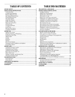
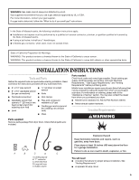
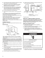
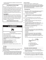
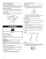
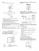
It is also recommended that a separate circuit serving only this dryer be provided. GROUNDING INSTRUCTIONS ■ For a grounded, cord-connected dryer: This dryer must be grounded. In the event of malfunction or breakdown, grounding will reduce the risk of electric shock by providing a path of least resistance for electric current. This dryer is equipped with a cord having an equipmentgrounding conductor and a grounding plug. The plug must be plugged into an appropriate outlet that is properly installed and grounded in accordance with all local codes and ordinances. WARNING: Improper connection of the equipment- grounding conductor can result in a risk of electric shock. Check with a qualified electrician or service representative or personnel if you are in doubt as to whether the dryer is properly grounded. Do not modify the plug provided with the dryer: if it will not fit the outlet, have a proper outlet installed by a qualified electrician. SAVE THESE INSTRUCTIONS Gas Supply Requirements WARNING Explosion Hazard Use a new CSA International approved gas supply line. Install a shut-off valve. Securely tighten all gas connections. If connected to LP, have a qualified person make sure gas pressure does not exceed 13" (330 mm) water column. Examples of a qualified person include: licensed heating personnel, authorized gas company personnel, and authorized service personnel. Failure to do so can result in death, explosion, or fire. Gas Type Natural Gas: This dryer is equipped for use with Natural gas. It is design-certified by CSA International for LP (propane or butane) gases with appropriate conversion. ■ Your dryer must have the correct burner for the type of gas in your home. Burner information is located on the rating plate in the door well of your dryer. If this information does not agree with the type of gas available, contact your dealer or call the phone numbers referenced on the front page of this manual. LP gas conversion: Conversion must be made by a qualified technician. No attempt shall be made to convert the appliance from the gas specified on the model/serial rating plate for use with a different gas without consulting your gas company. For information on ordering an LP conversion kit, please refer to the "Assistance or Service" section. Ask for Part Number 49572. Gas Supply Line: ■ Must include 1/8" NPT minimum plugged tapping accessible for test gauge connection, immediately upstream of the gas connection to the dryer (see illustration). ■ 1/2" IPS pipe is recommended. ■ 3/8" approved aluminum or copper tubing is acceptable for lengths under 20 ft (6.1 m) if local codes and gas supplier permit. ■ If you are using Natural gas, do not use copper tubing. ■ 3/8" flare x 3/8" NPT adapter fitting between dryer pipe and 3/8" approved tubing. ■ Lengths over 20 ft (6.1 m) should use larger tubing and a different size adapter fitting. ■ If your dryer has been converted to use LP gas, 3/8" LP compatible copper tubing can be used. If the total length of the supply line is more than 20 ft (6.1 m), use larger pipe. NOTE: Pipe-joint compounds that resist the action of LP gas must be used. Do not use TEFLON®† tape. ■ Must include a shutoff valve: In the U.S.A.: An individual manual shutoff valve must be installed within six (6) feet (1.8 m) of the dryer in accordance with the National Fuel Gas Code, ANSI Z223.1. In Canada: An individual manual shutoff valve must be installed in accordance with the B149.1, Natural Gas and Propane Installation Code. It is recommended that an individual manual shutoff valve be installed within six (6) feet (1.8 m) of the dryer. The location should be easy to reach for opening and closing. C E A D B A. 3/8" flexible gas connector B. 3/8" pipe to flare adapter fitting C. 1/8" NPT minimum plugged tapping D. 1/2" NPT gas supply line E. Gas shutoff valve Gas supply connection requirements ■ Use an elbow and a 3/8" flare x 3/8" NPT adapter fitting between the flexible gas connector and the dryer gas pipe, as needed to avoid kinking. ■ Use only pipe-joint compound. Do not use TEFLON®† tape. ■ This dryer must be connected to the gas supply line with a listed flexible gas connector that complies with the standard for connectors for gas appliances, ANSI Z21.24 or CSA 6.10. †®TEFLON is a registered trademark of E.I. Du Pont De Nemours and Company. 7
-
 1
1 -
 2
2 -
 3
3 -
 4
4 -
 5
5 -
 6
6 -
 7
7 -
 8
8 -
 9
9 -
 10
10 -
 11
11 -
 12
12 -
13
-
14
-
15
-
16
-
17
-
18
-
19
-
20
-
21
-
22
-
23
-
24
-
25
-
26
-
27
-
28
-
29
-
30
-
31
-
32
-
33
-
34
-
35
-
36
-
37
-
38
-
39
-
40
-
41
-
42
-
43
-
44
-
45
-
46
-
47
-
48
-
49
-
50
-
51
-
52
 |
 |