Whirlpool WMH1162XVD Installation Instructions - Page 2
Installationrequirements - instructions
 |
UPC - 883049147901
View all Whirlpool WMH1162XVD manuals
Add to My Manuals
Save this manual to your list of manuals |
Page 2 highlights
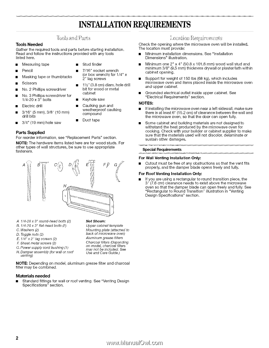
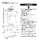
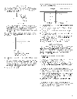
INSTALLATIONREQUIREMENTS Tools Needed Gather the required tools and parts before starting installation. Read and follow the instructions provided with any tools listed here. • Measuring tape • Stud finder • Pencil • 7/16" socket wrench • Masking tape or thumbtacks (or box wrench) for 1/4" x 2" lag screws • Scissors • 11/2"(3.8 cm) diam. hole drill • No. 2 Phillips screwdriver bit for wood or metal • No. 3 Phillips screwdriver for cabinet 1/4-20 x 3" bolts • Keyhole saw • Electric drill • 3d/r1ill6"bit(s5 mm), 3/8" (10 mm) • 3/4" (19 mm) hole saw • Caulking gun and weatherproof caulking compound • Duct tape Parts Supplied For reorder information, see "Replacement Parts" section. NOTE: The hardware items listed here are for wood studs. For other types of wall structures, be sure to use appropriate fasteners. A Check the opening where the microwave oven will be installed. The location must provide: • Minimum installation dimensions. See "Installation Dimensions" illustration. Minimum one 2" x 4" (50.8 x 101.6 mm) wood wall stud and minimum 3/8" (9.5 mm) thickness drywall or plaster/lath within cabinet opening. Support for weight of 150 Ibs (68 kg), which includes microwave oven and items placed inside the microwave oven and upper cabinet. Grounded electrical outlet inside upper cabinet. See "Electrical Requirements" section. NOTES: • If installing the microwave oven near a left sidewall, make sure there is at least 6" (15.2 cm) of clearance between the wall and the microwave oven, so that the door can open fully. Some cabinet and building materials are not designed to withstand the heat produced by the microwave oven for cooking. Check with your builder or cabinet supplier to make sure that the materials used will not discolor, delaminate or sustain other damages. Special Requirements For Wall Venting Installation Only: • Cutout must be free of any obstructions so that the vent fits properly, and the damper blade opens freely and fully. For Roof Venting Installation Only: • If you are using a rectangular to round transition piece, the 3" (7.6 cm) clearance needs to exist above the microwave oven so that the damper blade can open freely and fully. See "Rectangular to Round Transition" illustration in "Venting Design Specifications" section. A 1/4-20 x 3" round-head bolts (2) B. 1/4-20 x 3" flat-head bolts (2) C. Washers (2) D. Toggle nuts (2) E. 1/4" x 2" lag screws (2) F. Sheet metal screws (2) G. Power supply cord bushing (1) H. Damper assembly (for wall or roof venting) Not Shown: Upper cabinet template Mounting plate (attached to back of microwave oven) Aluminum grease filters Charcoal filters (Depending on model, charcoal filters may not be included. See Use and Care Guide.) NOTE: Depending on model, aluminum grease filter and charcoal filter may be combined. Materials needed • Standard fittings for wall or roof venting. See "Venting Design Specifications" section. 2
-
 1
1 -
 2
2 -
 3
3 -
 4
4 -
 5
5 -
 6
6 -
 7
7 -
 8
8 -
9
-
10
-
11
-
12
 |
 |