Whirlpool WMH1162XVD Installation Instructions - Page 8
boltsandtogglenutsor1/4x2lag - dimensions
 |
UPC - 883049147901
View all Whirlpool WMH1162XVD manuals
Add to My Manuals
Save this manual to your list of manuals |
Page 8 highlights
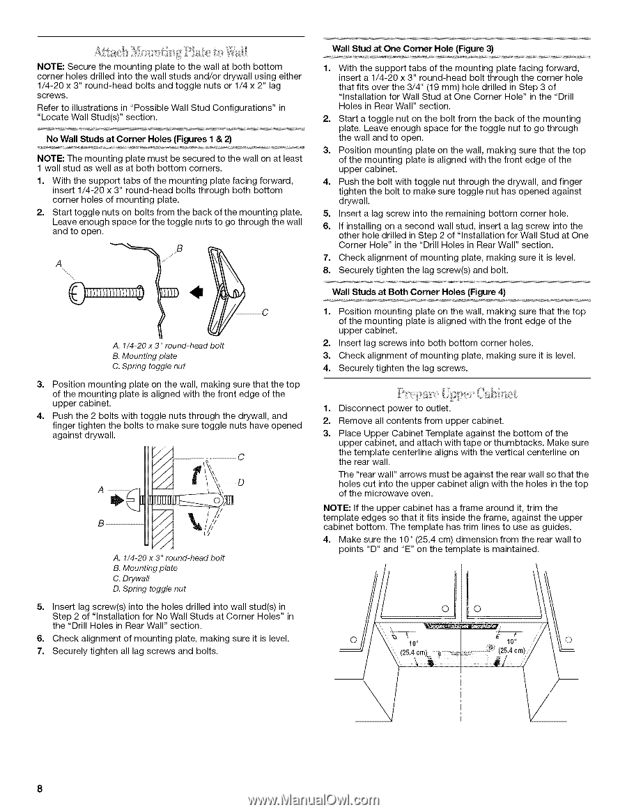
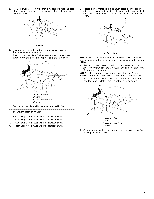
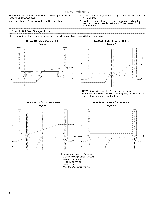
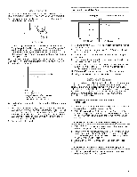
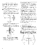
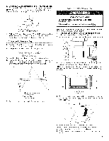
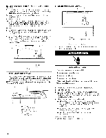
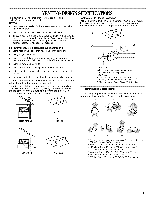
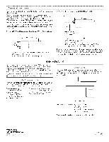
NOTES: ecurtehemountinpglatetothewallatbothbottom cornehrolesdrilledintothewallstudsand/odrrywaullsingeither 1/4-20x 3"round-heabdoltsandtogglenutsor1/4x2"lag screws. Refetroillustrationins"PossibWle alSl tudConfigurationins" "LocatWe alSl tud(ss)"ection. No Wall Studs at Corner Holes (Figures I & 2) NOTE: The mounting plate must be secured to the wall on at least 1 wall stud as well as at both bottom corners. 1. With the support tabs of the mounting plate facing forward, insert 1/4-20 x 3" round-head bolts through both bottom corner holes of mounting plate. 2. Start toggle nuts on bolts from the back of the mounting plate. Leave enough space for the toggle nuts to go through the wall and to open. Wall Stud at One Corner Hole (Figure 3) 1. With the support tabs of the mounting plate facing forward, insert a 1/4-20 x 3" round-head bolt through the corner hole that fits over the 3/4" (19 mm) hole drilled in Step 3 of "Installation for Wall Stud at One Corner Hole" in the "Drill Holes in Rear Wall" section. 2. Start a toggle nut on the bolt from the back of the mounting plate. Leave enough space for the toggle nut to go through the wall and to open. 3. Position mounting plate on the wall, making sure that the top of the mounting plate is aligned with the front edge of the upper cabinet. 4. Push the bolt with toggle nut through the drywall, and finger tighten the bolt to make sure toggle nut has opened against drywall. 5. Insert a lag screw into the remaining bottom corner hole. 6. If installing on a second wall stud, insert a lag screw into the other hole drilled in Step 2 of "Installation for Wall Stud at One Corner Hole" in the "Drill Holes in Rear Wall" section. 7. Check alignment of mounting plate, making sure it is level. 8. Securely tighten the lag screw(s) and bolt. Wall Studs at Both Corner Holes (Figure 4) A. 1/4-20 x 3" round-head bolt B. Mounting plate C. Spring toggle nut 1. Position mounting plate on the wall, making sure that the top of the mounting plate is aligned with the front edge of the upper cabinet. 2. Insert lag screws into both bottom corner holes. 3. Check alignment of mounting plate, making sure it is level. 4. Securely tighten the lag screws. 3. Position mounting plate on the wall, making sure that the top of the mounting plate is aligned with the front edge of the upper cabinet. 4. Push the 2 bolts with toggle nuts through the drywall, and finger tighten the bolts to make sure toggle nuts have opened against drywall. 1. Disconnect power to outlet. 2. Remove all contents from upper cabinet. 3. Place Upper Cabinet Template against the bottom of the upper cabinet, and attach with tape or thumbtacks. Make sure the template centerline aligns with the vertical centerline on //// ......i C the rear wall. // = L The "rear wall" arrows must be against the rear wall so that the holes cut into the upper cabinet align with the holes in the top of the microwave oven. // // .// // A. 1/4-20 x 3" round-head bolt B. Mounting plate C. Drywall D. Spring toggle nut NOTE: If the upper cabinet has a frame around it, trim the template edges so that it fits inside the frame, against the upper cabinet bottom. The template has trim lines to use as guides. 4. Make sure the 10" (25.4 cm) dimension from the rear wall to points "D" and "E" on the template is maintained. 5. Insert lag screw(s) into the holes drilled into wall stud(s) in Step 2 of "Installation for No Wall Studs at Corner Holes" in the "Drill Holes in Rear Wall" section. O O 6. Check alignment of mounting plate, making sure it is level. 7. Securely tighten all lag screws and bolts. o 10" E 10" o (25.4 cm)/ 8
-
 1
1 -
2
-
 3
3 -
 4
4 -
 5
5 -
 6
6 -
 7
7 -
 8
8 -
 9
9 -
 10
10 -
 11
11 -
 12
12
 |
 |