Whirlpool WVI75UC6DS Use & Care Guide - Page 9
Warning
 |
View all Whirlpool WVI75UC6DS manuals
Add to My Manuals
Save this manual to your list of manuals |
Page 9 highlights
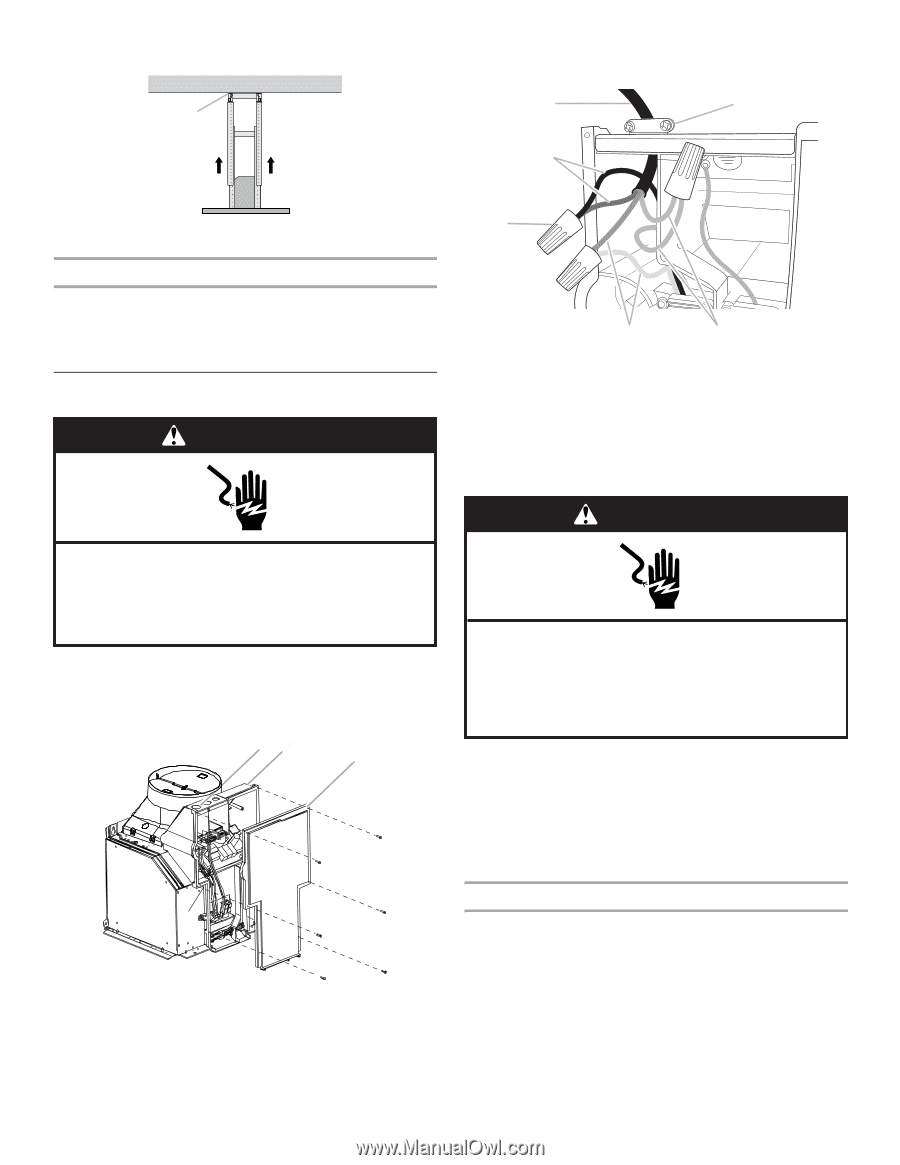
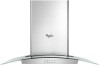
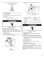
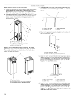
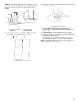
2. Install 16 - 4.2 x 8 mm screws and tighten to secure. A 4. Run home power supply cable through strain relief, into terminal box. A B C A. Mounting screws Connect Vent System 1. Install vent system. 2. Push duct over the exhaust outlet. Seal all connections with vent clamps. 3. Use caulk to seal all openings. Make Electrical Connection WARNING Electrical Shock Hazard Disconnect power before servicing. Replace all parts and panels before operating. Failure to do so can result in death or electrical shock. 1. Disconnect power. 2. Remove terminal box cover. 3. Remove the knockout in the terminal box and install a UL listed or CSA approved ¹⁄₂" strain relief. AB C A. Knockout B. Terminal box C. Terminal box cover D E F A. Home power supply cable B. UL listed or CSA approved strain relief C. Black wires D. UL listed wire connectors E. White wires F. Green (or bare) and yellowgreen ground wires 5. Use UL listed wire connectors and connect black wires (C) together. 6. Use UL listed wire connectors and connect white wires (E) together. WARNING Electrical Shock Hazard Electrically ground blower. Connect ground wire to green and yellow ground wire in terminal box. Failure to do so can result in death or electrical shock. 7. Connect green (or bare) ground wire from home power supply to yellow-green ground wire (F) in terminal box using UL listed wire connectors. 8. Tighten strain relief screw. 9. Install terminal box cover. 10. Check that all light bulbs are secure in their sockets. 11. Reconnect power. Optional Power Cord Kit Installations For optional power cord kit installations, follow the instructions supplied with the power cord kit. See the "Assistance or Service" section for information on ordering. NOTE: Use only with range hood cord connection kits that have been investigated and found acceptable for use with this model range hood. 9
-
 1
1 -
2
-
3
-
 4
4 -
 5
5 -
 6
6 -
 7
7 -
 8
8 -
 9
9 -
 10
10 -
 11
11 -
 12
12 -
 13
13 -
 14
14 -
15
-
16
-
17
-
18
-
19
-
20
-
21
-
22
-
23
-
24
-
25
-
26
-
27
-
28
-
29
-
30
-
31
-
32
 |
 |