Yamaha 01V96 Studio Manager Owner's Manual
Yamaha 01V96 Manual
 |
View all Yamaha 01V96 manuals
Add to My Manuals
Save this manual to your list of manuals |
Yamaha 01V96 manual content summary:
- Yamaha 01V96 | Studio Manager Owner's Manual - Page 1
Studio Manager for Owner's Manual E - Yamaha 01V96 | Studio Manager Owner's Manual - Page 2
digital audio files is strictly prohibited except for your personal use. • The screen displays as illustrated in this owner's manual are for instructional purposes, and may appear somewhat different from the screens which appear on your computer. • Future upgrades of application and system software - Yamaha 01V96 | Studio Manager Owner's Manual - Page 3
5 Patch Editor Window 25 INPUT PATCH Page 25 OUTPUT PATCH Page 26 INSERT PATCH Page 27 EFFECT PATCH Page 28 DIRECT OUT Patch Page 29 6 Surround Editor Window 30 7 Effect Editor Window 31 8 Keyboard Shortcuts 32 File Menu 32 Windows Menu 32 Index 33 Studio Manager for 01V96-Owner's Manual - Yamaha 01V96 | Studio Manager Owner's Manual - Page 4
to which your 01V96 is connected (e.g., MIDI In, Out, or Thru). Note: To use a MIDI port with Studio Manager, you must select it on the MIDI Setup dialog box (as explained above) and on the System Setup dialog box, as explained on page 5. Warning: Studio Manager does not yet support OPT (Open Plug - Yamaha 01V96 | Studio Manager Owner's Manual - Page 5
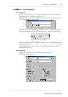
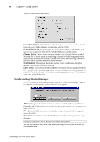
that Studio Manager should use to communicate with the 01V96. Windows: Choose System Setup from the File menu, and specify the input and output ports on the Setup dialog box, as shown below. Macintosh: Choose Select OMS Ports from the File menu, and specify the input and output ports (device names - Yamaha 01V96 | Studio Manager Owner's Manual - Page 6
Getting Started This is the Macintosh Setup window Input Port/Output Port: (Windows only) These pop-up menus are used to select the ports with which Studio Manager communicates with the 01V96. Console Device ID: Studio Manager can control any one of up to eight 01V96s, each with its own exclusive - Yamaha 01V96 | Studio Manager Owner's Manual - Page 7
order to save the settings of an optional Y56K card, in a Session, you must resynchronize Studio Manager beforehand (Console->PC). Note: In order to protect the communication port used by Studio Manager, 01V96 communication settings (e.g., MIDI, Remote Layer, Machine Control) are not affected by PC - Yamaha 01V96 | Studio Manager Owner's Manual - Page 8
. Many functions can be operated from here by clicking and dragging the various controls and parameters. This is explained in the following sections. Channels can be viewed in more detail on the Selected Channel window. See page 15 for more information. Studio Manager for 01V96-Owner's Manual - Yamaha 01V96 | Studio Manager Owner's Manual - Page 9
's curve. M EQ button This button is used to turn on and off the Input Channel's EQ. N EQ curve This display shows the Equalizer's curve, which can be set by dragging. O DELAY button This button is used to turn on and off the Input Channel's Delay function. Studio Manager for 01V96-Owner's Manual - Yamaha 01V96 | Studio Manager Owner's Manual - Page 10
appears orange while the channel is on. Y Short channel name This is the channel's short name. To edit the name, click it and type. Z Channel fader This is the Input Channel's fader. a Channel meter This meter displays the signal level of the Input Channel. Studio Manager for 01V96-Owner's Manual - Yamaha 01V96 | Studio Manager Owner's Manual - Page 11
either channel R or L to operate by the PAN control (J). M SOLO button This button solos the Input Channel. It appears orange while the channel is soloed. N ON button This button turns the Input Channel on and off. It appears orange while the channel is on. Studio Manager for 01V96-Owner's Manual - Yamaha 01V96 | Studio Manager Owner's Manual - Page 12
the Selected Channel window. 7 F ON button This button turns the Stereo Out on and off. It appears orange while the Stereo Out is on. G Channel fader This is the Stereo Out fader. Studio Manager for 01V96-Owner's Manual - Yamaha 01V96 | Studio Manager Owner's Manual - Page 13
Channel number This is the channel number. J SELECT button J This button is used to select the Bus Out. K L K SOLO button M This button solos fader This is the Bus Out's fader. O Channel meter This meter displays the signal level of the Bus Out. Studio Manager for 01V96-Owner's Manual - Yamaha 01V96 | Studio Manager Owner's Manual - Page 14
- trol the functions specified on the Remote page. When the remote target is set to anything other than User Defined, the ON buttons and channel faders have no effect, and the name of the specified target is displayed in the channel's short name. 2 C D 5 Studio Manager for 01V96-Owner's Manual - Yamaha 01V96 | Studio Manager Owner's Manual - Page 15
below the Channel ID. To edit the name, click it and type. The INPUT PATCH parameter is used to select an input source. To select an input, click the parameter and choose from the list that appears. The LIBRARY button opens the Channel Library window. Studio Manager for 01V96-Owner's Manual - Yamaha 01V96 | Studio Manager Owner's Manual - Page 16
Input Channel. The INSERT button turns the Insert on and off. The OUT and IN parameters are used to specify the insert out destination and insert in source respectively. The POSITION parameter is used to specify the position of the Insert in the signal path. Studio Manager for 01V96-Owner's Manual - Yamaha 01V96 | Studio Manager Owner's Manual - Page 17
Use the FADER GROUP buttons to add the channel to Fader groups, and use the MUTE GROUP buttons to add it to Mute groups. Stereo Input Channels This is the Selected Channel window for Input Channels. 1 23 45 6 A CHANNEL SELECT, INPUT the EQ Library window. Studio Manager for 01V96-Owner's Manual - Yamaha 01V96 | Studio Manager Owner's Manual - Page 18
for the currently selected Stereo Input Channel. Use the FADER GROUP buttons to add the channel to Fader groups, and use the MUTE GROUP buttons to add it to Mute groups. Bus Outs This is the Selected Channel window for Bus Outs. 1 2 3 4 5 6 7 Studio Manager for 01V96-Owner's Manual - Yamaha 01V96 | Studio Manager Owner's Manual - Page 19
the EQ controls and display graph for the currently selected Bus Out. It's layout is identical to the EQUALIZER section for Input Channels. Use the FADER GROUP buttons to add the channel to Fader groups, and use the MUTE GROUP buttons to add it to Mute groups. Studio Manager for 01V96-Owner's Manual - Yamaha 01V96 | Studio Manager Owner's Manual - Page 20
Aux Send. E COMPRESSOR section This section contains the Compressor controls and display graph for the currently selected Aux Send. Its layout is identical to the COMPRESSOR section for Input Channels. See "COMPRESSOR section" on page 16 for more information. Studio Manager for 01V96-Owner's Manual - Yamaha 01V96 | Studio Manager Owner's Manual - Page 21
opens the Channel Library window. B EQUALIZER section This section contains the EQ controls and display graph for the Stereo Out. It's layout is identical to the EQUALIZER section for Input Channels. See "EQUALIZER section" on page 16 for more information. Studio Manager for 01V96-Owner's Manual - Yamaha 01V96 | Studio Manager Owner's Manual - Page 22
for the currently selected Remote Channel. 2 Note: When the remote target setting on the 01V96 is set to anything other than User Defined, the ON buttons and channel faders have no effect, and the name of the specified target is displayed below the channel ID. Studio Manager for 01V96-Owner's Manual - Yamaha 01V96 | Studio Manager Owner's Manual - Page 23
, click and then type. 12 3 4 5 KJ 6 L7 8 9 M A File name This is the file name of the currently open Library file. B OPEN button This button is used to open Library files. C CLOSE button This button is used to close the currently open Library file. NO P Studio Manager for 01V96-Owner's Manual - Yamaha 01V96 | Studio Manager Owner's Manual - Page 24
pane displays a padlock icon for protected memories. H INPUT PATCH LINK pane This pane displays the number of the linked input patch memory. I OUTPUT PATCH LINK pane This . P PROTECT button This button is used to protect or unprotect the selected memory. Studio Manager for 01V96-Owner's Manual - Yamaha 01V96 | Studio Manager Owner's Manual - Page 25
on this page. E LIBRARY button This button opens the Input Patch Library window. F Patchbay The patchbay is used to patch input ports to Input Channels. Active patches are indicated by a blue dot. To make a patch, click a square. To unpatch, click a blue dot. Studio Manager for 01V96-Owner's Manual - Yamaha 01V96 | Studio Manager Owner's Manual - Page 26
on this page. E LIBRARY button This button opens the Output Patch Library window. F Patchbay The patchbay is used to patch output ports to Output Channels. Active patches are indicated by a red dot. To make a patch, click a square. To unpatch, click a red dot. Studio Manager for 01V96-Owner's Manual - Yamaha 01V96 | Studio Manager Owner's Manual - Page 27
a red dot. E Insert In Patchbay This patchbay is used to patch input ports to the Insert Ins of Input Channels, Bus Outs, Aux Sends, and the Stereo Out. Active patches are indicated by a blue dot. To make a patch, click a square. To unpatch, click a blue dot. Studio Manager for 01V96-Owner's Manual - Yamaha 01V96 | Studio Manager Owner's Manual - Page 28
28 Chapter 5-Patch Editor Window EFFECT PATCH Page 1 2 A Effects processor #1-#4 inputs These parameters are used to select input sources for internal effects processors #1-#4. B LIBRARY button This button opens the Input Patch Library window. Studio Manager for 01V96-Owner's Manual - Yamaha 01V96 | Studio Manager Owner's Manual - Page 29
it and type. C LIBRARY button This button opens the Output Patch Library window. D Patchbay The patchbay is used to patch output ports to the Direct Outs. Active patches are indicated by a red dot. To make a patch, click a square. To unpatch, click a red dot. Studio Manager for 01V96-Owner's Manual - Yamaha 01V96 | Studio Manager Owner's Manual - Page 30
rear. The DIV.F control sets the amount of divergence for the front signal. G DIV.R control (6.1 only) This rotary control sets the amount of divergence for the rear signal. H LINK button (6.1 only) This button is used to link the DIV.F and DIV.R controls. Studio Manager for 01V96-Owner's Manual - Yamaha 01V96 | Studio Manager Owner's Manual - Page 31
This control is used to adjust the balance between the wet and dry signals. When set to 0, only the dry signal is heard. When set to 100, only the wet signal is heard. H BYPASS button This button is used to bypass the currently selected effects processor. Studio Manager for 01V96-Owner's Manual - Yamaha 01V96 | Studio Manager Owner's Manual - Page 32
Action Closes the foremost window except the Console window Closes all windows except the Console window Opens the Selected Channel window Opens the Library window Opens the Patch Editor window Opens the Surround Editor window Opens the Effect Editor window Studio Manager for 01V96-Owner's Manual - Yamaha 01V96 | Studio Manager Owner's Manual - Page 33
control (6.1 only) 30 E Effect editor window 31 EFFECT NAME 31 Effect parameter section 31 Effect patch page 28 EFFECT TYPE 31 Effects library 23 Effects processor #1-#4 inputs 28 EQ button 9, 11, 13 EQ curve 9, 11, 13, 16, 17 EQ library 23 EQUALIZER section 16, 17, 19, 20, 21 Exiting Studio Manager - Yamaha 01V96 | Studio Manager Owner's Manual - Page 34
confirmation 6 SURR button 12 Surround editor window 30 SURROUND MODE indicator 30 Surround pan graph 30 Surround pan position 30 Synchronizing Studio Manager 6 T Title pane 24 TO STEREO section 19 TYPE I button 16, 17 TYPE II button 16, 17 U UNDO button 24 Studio Manager for 01V96-Owner's Manual - Yamaha 01V96 | Studio Manager Owner's Manual - Page 35
35 Y Yamaha Web Site 2 Studio Manager for 01V96-Owner's Manual - Yamaha 01V96 | Studio Manager Owner's Manual - Page 36
Yamaha Manual Library http://www2.yamaha.co.jp/manual/english/ M.D.G., Pro Audio & Digital Musical Instrument Division, Yamaha Corporation © 2003 Yamaha Corporation IP01A0
-
 1
1 -
 2
2 -
 3
3 -
 4
4 -
 5
5 -
 6
6 -
 7
7 -
8
-
9
-
10
-
11
-
12
-
13
-
14
-
15
-
16
-
17
-
18
-
19
-
20
-
21
-
22
-
23
-
24
-
25
-
26
-
27
-
28
-
29
-
30
-
31
-
32
-
33
-
34
-
35
-
36
 |
 |

Studio Manager
for
Owner’s Manual
E