Yamaha CVP-309 Owner's Manual - Page 209
CVP-309/307: Keyboard Stand Assembly
 |
View all Yamaha CVP-309 manuals
Add to My Manuals
Save this manual to your list of manuals |
Page 209 highlights
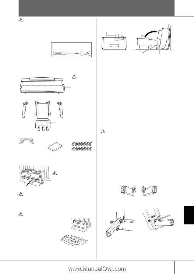
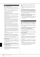
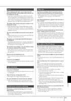
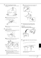
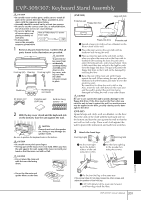
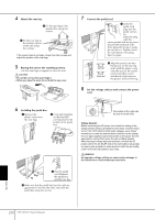
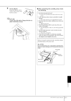
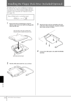
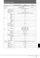
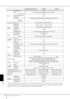
CVP-309/307: Keyboard Stand Assembly CAUTION • Be careful not to confuse parts, and be sure to install all parts in the correct direction. Please assemble in accor- dance with the sequence given below. • Assembly should be carried out by at least two persons. • Be sure to use the correct screw size, as indicated below. Use of incorrect screws can cause damage. • Be sure to tighten up all screws upon completing assembly of Have a Phillips-head (+) screwdriver ready. each unit. • To disassemble, reverse the assembly sequence given below. 1 Remove all parts from the box. Confirm that all parts shown in the illustration are provided. Front leg (left) Rear leg Front leg (right) CAUTION To prevent the key cover from accidentally opening during assembly, press down on the key cover, making sure that the sheet (shown) remain in place. Pedal box AC power cord Bundled pedal cord inside Protective pad (CVP-309) 5x18 mm fixing screws × 14 2 With the key cover closed and the keyboard side on the bottom, lean the unit against the wall. CAUTION Please do not touch the speaker net. Doing so may damage the speaker inside. Be sure to position the keyboard side on the bottom. CAUTION • Be careful not to pinch your fingers. • The top part of the music rest is not fixed. When you lean the unit against the wall, support the music rest with your hand so that the music rest will not fall. CAUTION • Do not place the main unit with the rear side facing down. (CVP-309) Protective pad Floppy disk drive Large soft cloth Floppy disk drive Protective pad 1 Spread a large soft cloth such as a blanket on the floor in front of the wall. 2 Place the main unit on the soft cloth with its keyboard side facing the wall. 3 Place a protective pad on the soft cloth, so that, when you place the main unit on the floor with its keyboard side touching the floor, the pad comes under the keyboard side, and is located about 10cm (a little more than four inches) to the high key side from the floppy disk drive. The pad will protect the floppy disk drive so that it will not be damaged by touching the floor. 4 Raise the rear of the main unit until it leans against the wall. When raising the unit, place the keyboard side at the bottom and make it sit on the protective pad. Be careful not to allow the unit to fall or slip. Also, insert the soft cloth between the main unit and the wall to protect the unit from being damaged by hitting the wall or any other object. CAUTION Be sure to use a protective pad to avoid a damage to the floppy disk drive. If the drive touches the floor when you raise the unit to lean it against the wall, too much pressure may be applied to the drive, possibly causing serious damages to the drive. (CVP-307) Spread a large soft cloth, such as a blanket, on the floor. Place the unit on the cloth with the keyboard side on the bottom and lean the unit against the wall so that the unit will not fall or slip. Place a soft cloth against the wall to protect the instrument and wall from scratches. 3 Attach the front legs. Front leg (right) Front leg (left) 1 Fix the front right leg to the bottom surface of the unit using two screws. 2 Fix the front right leg to the speaker box using two screws. Appendix • Do not lay the main unit upside-down on the floor. Incorrect Incorrect 3 Fix the front left leg in the same way. If the screw holes do not align, loosen the other screws and adjust the position of the front leg. 4(CVP-309) Slowly tilt the main unit forward until front legs reach the floor. CVP-309/307 Owner's Manual 209
-
 1
1 -
2
-
3
-
4
-
5
-
6
-
7
-
8
-
9
-
10
-
11
-
12
-
13
-
14
-
15
-
16
-
17
-
18
-
19
-
20
-
21
-
22
-
23
-
24
-
25
-
26
-
27
-
28
-
29
-
30
-
31
-
32
-
33
-
34
-
35
-
36
-
37
-
38
-
39
-
40
-
41
-
42
-
43
-
44
-
45
-
46
-
47
-
48
-
49
-
50
-
51
-
52
-
53
-
54
-
55
-
56
-
57
-
58
-
59
-
60
-
61
-
62
-
63
-
64
-
65
-
66
-
67
-
68
-
69
-
70
-
71
-
72
-
73
-
74
-
75
-
76
-
77
-
78
-
79
-
80
-
81
-
82
-
83
-
84
-
85
-
86
-
87
-
88
-
89
-
90
-
91
-
92
-
93
-
94
-
95
-
96
-
97
-
98
-
99
-
100
-
101
-
102
-
103
-
104
-
105
-
106
-
107
-
108
-
109
-
110
-
111
-
112
-
113
-
114
-
115
-
116
-
117
-
118
-
119
-
120
-
121
-
122
-
123
-
124
-
125
-
126
-
127
-
128
-
129
-
130
-
131
-
132
-
133
-
134
-
135
-
136
-
137
-
138
-
139
-
140
-
141
-
142
-
143
-
144
-
145
-
146
-
147
-
148
-
149
-
150
-
151
-
152
-
153
-
154
-
155
-
156
-
157
-
158
-
159
-
160
-
161
-
162
-
163
-
164
-
165
-
166
-
167
-
168
-
169
-
170
-
171
-
172
-
173
-
174
-
175
-
176
-
177
-
178
-
179
-
180
-
181
-
182
-
183
-
184
-
185
-
186
-
187
-
188
-
189
-
190
-
191
-
192
-
193
-
194
-
195
-
196
-
197
-
198
-
199
-
200
-
201
-
202
-
203
-
 204
204 -
 205
205 -
 206
206 -
 207
207 -
 208
208 -
 209
209 -
 210
210 -
 211
211 -
 212
212 -
 213
213 -
 214
214 -
215
-
216
-
217
-
218
-
219
-
220
-
221
-
222
-
223
-
224
 |
 |